


10pcs Dual 2 Mode PWM Square Rectangular Signal Generator Control DC Stepper Motor Driver Board Adjustable Pulse Module
$75.25
Shipping:Standard Shipping about 10-25 business days
Secure Payment:Paypal,VISA,MasterCard
Size Conversion
Inches
Centimeters
Please according to your own measurements to choose your suitable size. The tags inside the items will show in our Asian (Type) size.
Feature
1. PWM signal generator, square rectangular signal generator
2. Used to generate square rectangular signals for controlling DC motor or stepper motor driver; used for servo motor, stepping motor, electric gripper, replacing PLC pulse, etc.
3. The supporting driver realizes dimming, speed regulation, control of solenoid , etc., but can not directly drive the load of the electric motor solenoid .
Product Highlights
1. Two modes can be selected
PWM mode – frequency (continuous), duty cycle, pulse number adjustable;
PULSE pulse mode – positive pulse width time, negative pulse width time, delay start time, and the number of pulses are adjustable.
2. With start and stop button, can control the output and stop of the signal
3. Wide voltage input 3.3-30V, with anti-reverse protection, 5.08mm terminal wiring
Technical parameters
1. Working voltage:3.3~30V, with anti-reverse protection
2. Frequency:1Hz~150KHz, accuracy about 2%
3. Duty cycle:0-100%, 1% stepping
4. Number of pulses:1-9999, or infinite (display ‘—-‘ stands for infinity)
5. Delay output time:0.000s-9999s, the can be set 1ms
6. Positive and negative pulse width length:0.000s-9999s, the can be set 1ms
7. Signal loading capacity:less than 30mA
8. Output signal amplitude:amplitude is equal to the supply voltage
9. Product size:60 x 32 x 10mm
10. Product Weight:18g
11. Packing:Anti-static bag
PWM mode (display has ‘%’ for PWM mode)
1. The factory default mode is PWM mode, FREQ+ and FREQ-key set frequency, DUTY+ and DUTY-button set duty cycle; short press STOP button control signal output or stop, stop output is 0, the screen displays “OUT” mark as There is output, otherwise it stops output; the default factory frequency is 1KHZ and the duty cycle is 50%.
If you want to switch to PULSE pulse mode, long-press the SET button (more than 6 seconds), do not release, you will see the screen change, ‘%’ disappears, it is PULSE mode.
2. PULSE pulse mode (No ‘%’ on the right side of the display is displayed in PULSE mode)
The P+ and P- buttons set the positive pulse width time, the LCD screen shows up, the N+ and N- buttons set the negative pulse width time, the LCD screen displays downwards, the unit is seconds; short press the STOP button to control the signal output or stop, stop output It is 0, the screen displays “OUT” mark as output, otherwise it stops output; the default factory positive pulse width is 0.5 second, and the negative pulse width is 0.5 second.
Pulse number and delay time setting – In PULSE mode, press and hold the SET button for 2 seconds and then release, enter the pulse number and delay time setting interface, the screen displays SET, it will be turned off and cleared after entering. Output pulse; P+ and P- buttons set delay time, N+ and N- buttons set pulse number, factory default delay time is 0 seconds, pulse number is infinite (display —-); Press the button for 2 seconds, automatically return to the pulse interface, press the STOP button, after the delay setting time, start to send the set number of pulses, if the number of pulses is sent, it will automatically output 0, if the period is not sent, press the STOP button. The output pulse will be turned off and cleared, and the number of pulses set will be issued each time it is started.
Application Operation Examples
1. PWM output 20KHZ, 60% duty cycle:Select PWM mode, the frequency is set to 20.00, and the duty ratio is set to 060%.
2. The output is turned on for 0.6 seconds and turned off for 0.2 seconds. Infinite loop:select PULSE mode, the positive pulse width is set to 0.600, the negative pulse width is set to 0.200, the delay time is set to 0.000, and the number of pulses is set to — -.
3. Power on or press the start button, delay 5 seconds, then the output is turned on for 0.6 seconds, off 0.2 seconds, infinite loop:select PULSE mode, positive pulse width is set to 0.600, negative pulse width is set to 0.200, delay The time is set to 5.000 and the number of pulses is set to —-.
4. Power on or press the start button, delay 5 seconds, then output high level 10ms low level 10ms pulse 100:select PULSE mode, positive pulse width is set to 0.010, negative pulse width is set to 0.010, delay The time is set to 5.000 and the number of pulses is set to 0100.
5. Power-on delay for 10 seconds, then permanently output signal:select PULSE mode, the positive pulse width is set to a number greater than 0, the negative pulse width is set to 0, the delay time is set to 10.00 seconds, and the pulse number is infinite. (—-).
6. Other applications can explore or consult customer service
All setup parameters are not lost when they are turned off.
Package includes
10 x PWM signal generator
| Weight | 0.19 kg |
|---|
Related products
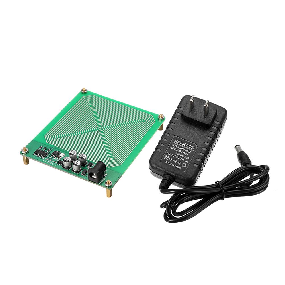
FM783 Schumann Wave Module Extremely Low Frequency Pulse Generator
$50.29Generator ModuleAdd to cartProduct technical parametersName:Schuhmann wave pole low frequency pulse generatorRated voltage:DC 12VRated current:1.5AApplicable voltage:100V-240V global general-purposeProduct accessories:wooden box finished products directly plug in electricity, standard 12V DC power supply.Know Schuhmann waveIn 1952, Schuhmann pointed out that the earth and the ionosphere could form a resonant cavity. There was a special resonant frequency in the cavity, which …
FM783 Schumann Wave Module Extremely Low Frequency Pulse GeneratorRead More
Schumann Wave Generator 7.83Hz 20W Power with Housing Low Frequency Generator 7.83HZ Sine Wave
$54.66Generator ModuleAdd to cartParameterProduct name:Schumann wave generator/very low frequency generatorMainboard power supply:DC 24V /2AOutput power:peak 20WAdapter power supply parameters:AC 100-240V 50HZOutput frequency:7.83HZOutput waveform:sine waveMotherboard size:9CM length * 5CM width * 2.5CM heightFeaturesSchumann wave itself does not directly act on audio or video products to improve the sound quality and picture quality, but on the space environment, the human …
3pcs NE555 Pulse Frequency Duty Cycle Square Wave Rectangular Wave Signal Generator Adjustable 555 Board NE555P Module
$11.41Generator ModuleAdd to cartFeatures-Size:3.5CM * 3.6CM-The main chip:NE555;-Input voltage:5V-15VDC. 5V power supply, the output current can about 15MA; 12V power supply, the output current can be so 35MA;-Input Current:100MA-Output amplitude:4.2V V-PP to 11.4V V-PP (depending on the input voltage, the output amplitude is not the same)-Maximum output current:15MA (5V power supply, V-PP greater than 50%), 35MA (12V power …


Customers Also Viewed
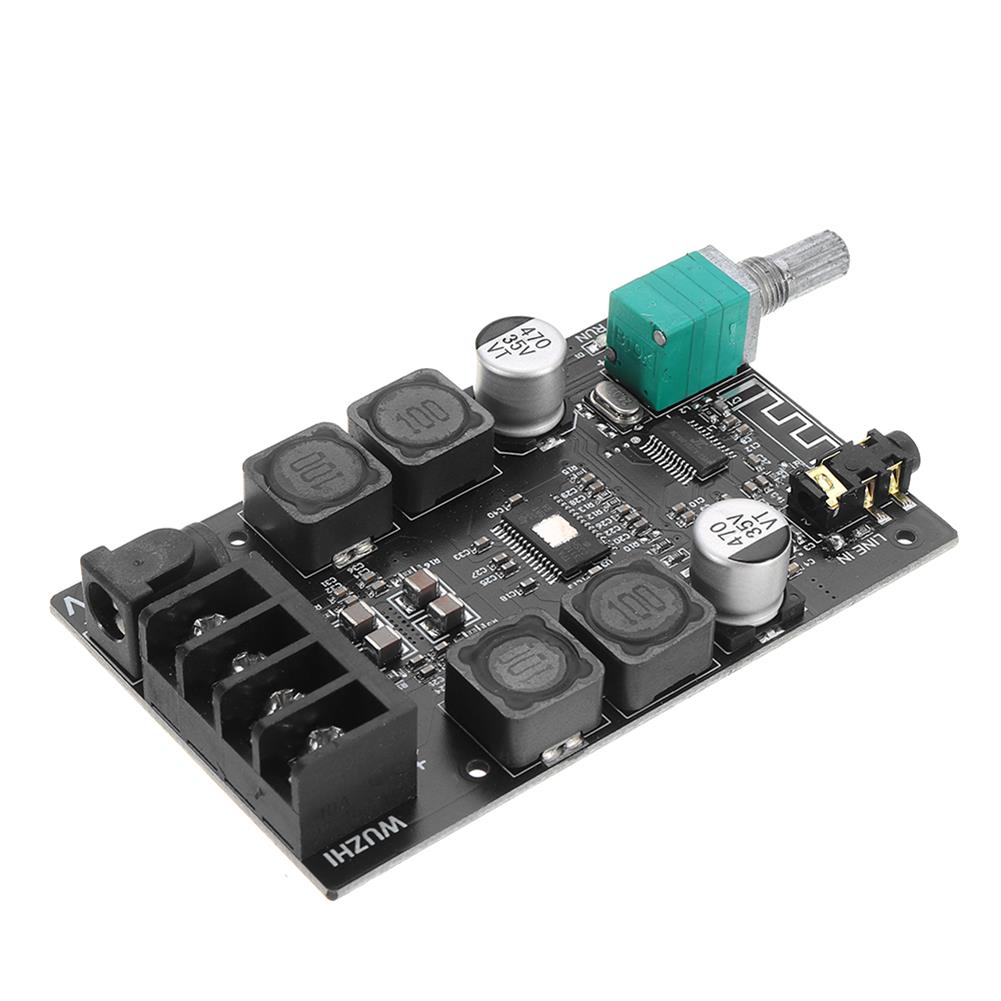
3pcs 2x50W TPA3116 AUX+Bluetooth 5.0 HIFI High Power Digital Amplifier Stereo Board AMP Amplificador Home theater without Shell
$54.90Amplifier BoardAdd to cartSpecificationsAudio input:AUX+bluetoothWork voltage:9-24 DCPower:2*50WCooling fin:LargeSpeaker:4-8Ω;30-200WProtection:Overvoltage,undervoltageSize:84*52*24mmFeatures1. This product is full of materials, featuring high performance and high performance price, especially for HIFI music power amplifier with high power and high fidelity.2. TPA3116D2 is a type D amplifier IC launched by TI company, which has very high index parameters.The maximum modulation frequency is 1.2MHZ, and the high …
5PCS USB To TTL Debug Serial Port Cable for Raspberry Pi 3B 2B / COM Port
$20.44Raspberry Pi & Orange PiAdd to cartMore info and driver, please !!!Supports WIN XP/WIN7/ WIN8/ WIN10Reference to WIN10, you can !!!NoteNo driver on raspberry pi 3 model bRaspberry Pi main board is not included!Package included5x USB To TTL Debug Serial Port Cable For Raspberry Pi / COM Port
DIY LED Light Kit ONLY for LEGO 60197 Passenger Train Building Block Bricks Lighting
$32.79DIY Electronic KitsAdd to cartSpecificationInterface:USBColor:As the picture shownThe product is just a light kit, not included the model!!!FitmentONLY For LEGO 60197 Passenger Train Building Block Bricks ToyFeaturesEasy to install.LED powered by USB.Make your model more cool.Package Included1 x LED Light Kit(Model Not Included)
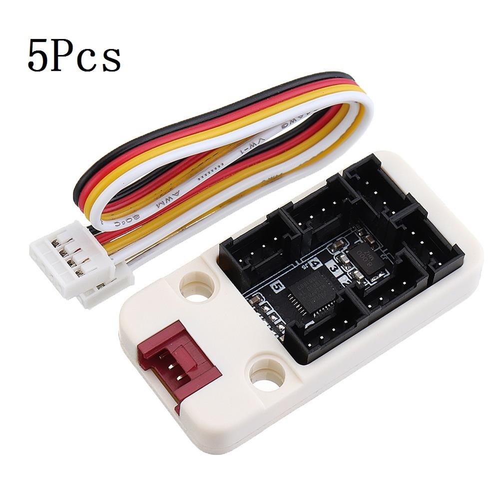
5Pcs M5Stack I/O Hub 1 to 6 Expansion Board Grove I/O interface for Blockly Development IoT MEGA328 Module for Arduino
$75.21Converter BoardAdd to cartDescriptionPbHUB, is a expander for singel-bus GROVE PORTB(Black port on M5GO Base). 1-to-6. PortB can be used as GPIO and analog in two data lines connected to GPIO36 and GPIO26 on ESP32. Same as PaHUB, it provides a solution for mutiple device control by PORTB. With PbHUB each of the IO can be configurated to …
10Pcs Green LED Power Symbol Momentary Latching Switch LED Light Push Button SPST
$20.86Electronic Accessories & SuppliesAdd to cart10Pcs Green LED Power Symbol Momentary Latching Switch LED Light Push Button SPSTDecriptionLatching type:Push it– on, push it again — offLED color:GreenSize(H*D):1.4 x 1cm / 0.55inch x 0.39inch (approx)Quantity:10 pcsFunction:MomentaryLED light voltage:3.2VSwitch voltage:12VMaximum operating current:20mAWith led light, with power symbol, light touch switchEasy to use and installNote1. Please check the picture and part number carefully …
10Pcs Green LED Power Symbol Momentary Latching Switch LED Light Push Button SPSTRead More
100Pcs Red Heat Shrink Solder Sleeve Seal Wire Splice Butt Connector AWG 22-18GA
$72.89ConnectorsAdd to cartName:(100) Heat Shrink Solder Sleeve Seal Wire Splice Butt Connector AWG 22-18GA RedMaterial:Tinned CopperColor:RedShrinking Ratio:2:1Working temperature:-55℃~125℃Shrink temperature:80℃Solder melting temperature:138℃Complete solder melting temperature:160℃Cable cross-section:0.5mm-1.0 mmDiameter:3mm/0.12inch(appr.)FeaturesPlacement on Vehicle:Left, Right, Front, Rear.Solder and seal and with advanced waterproof function.Polyolefin tubing in outside and hot melt adhesive in inside.Can be ideal used in marine and automobile applications.Improve pullout strength, …
100Pcs Red Heat Shrink Solder Sleeve Seal Wire Splice Butt Connector AWG 22-18GARead More


Reviews
There are no reviews yet.