


10pcs Dual 2 Mode PWM Square Rectangular Signal Generator Control DC Stepper Motor Driver Board Adjustable Pulse Module
$75.25
Shipping:Standard Shipping about 10-25 business days
Secure Payment:Paypal,VISA,MasterCard
Size Conversion
Inches
Centimeters
Please according to your own measurements to choose your suitable size. The tags inside the items will show in our Asian (Type) size.
Feature
1. PWM signal generator, square rectangular signal generator
2. Used to generate square rectangular signals for controlling DC motor or stepper motor driver; used for servo motor, stepping motor, electric gripper, replacing PLC pulse, etc.
3. The supporting driver realizes dimming, speed regulation, control of solenoid , etc., but can not directly drive the load of the electric motor solenoid .
Product Highlights
1. Two modes can be selected
PWM mode – frequency (continuous), duty cycle, pulse number adjustable;
PULSE pulse mode – positive pulse width time, negative pulse width time, delay start time, and the number of pulses are adjustable.
2. With start and stop button, can control the output and stop of the signal
3. Wide voltage input 3.3-30V, with anti-reverse protection, 5.08mm terminal wiring
Technical parameters
1. Working voltage:3.3~30V, with anti-reverse protection
2. Frequency:1Hz~150KHz, accuracy about 2%
3. Duty cycle:0-100%, 1% stepping
4. Number of pulses:1-9999, or infinite (display ‘—-‘ stands for infinity)
5. Delay output time:0.000s-9999s, the can be set 1ms
6. Positive and negative pulse width length:0.000s-9999s, the can be set 1ms
7. Signal loading capacity:less than 30mA
8. Output signal amplitude:amplitude is equal to the supply voltage
9. Product size:60 x 32 x 10mm
10. Product Weight:18g
11. Packing:Anti-static bag
PWM mode (display has ‘%’ for PWM mode)
1. The factory default mode is PWM mode, FREQ+ and FREQ-key set frequency, DUTY+ and DUTY-button set duty cycle; short press STOP button control signal output or stop, stop output is 0, the screen displays “OUT” mark as There is output, otherwise it stops output; the default factory frequency is 1KHZ and the duty cycle is 50%.
If you want to switch to PULSE pulse mode, long-press the SET button (more than 6 seconds), do not release, you will see the screen change, ‘%’ disappears, it is PULSE mode.
2. PULSE pulse mode (No ‘%’ on the right side of the display is displayed in PULSE mode)
The P+ and P- buttons set the positive pulse width time, the LCD screen shows up, the N+ and N- buttons set the negative pulse width time, the LCD screen displays downwards, the unit is seconds; short press the STOP button to control the signal output or stop, stop output It is 0, the screen displays “OUT” mark as output, otherwise it stops output; the default factory positive pulse width is 0.5 second, and the negative pulse width is 0.5 second.
Pulse number and delay time setting – In PULSE mode, press and hold the SET button for 2 seconds and then release, enter the pulse number and delay time setting interface, the screen displays SET, it will be turned off and cleared after entering. Output pulse; P+ and P- buttons set delay time, N+ and N- buttons set pulse number, factory default delay time is 0 seconds, pulse number is infinite (display —-); Press the button for 2 seconds, automatically return to the pulse interface, press the STOP button, after the delay setting time, start to send the set number of pulses, if the number of pulses is sent, it will automatically output 0, if the period is not sent, press the STOP button. The output pulse will be turned off and cleared, and the number of pulses set will be issued each time it is started.
Application Operation Examples
1. PWM output 20KHZ, 60% duty cycle:Select PWM mode, the frequency is set to 20.00, and the duty ratio is set to 060%.
2. The output is turned on for 0.6 seconds and turned off for 0.2 seconds. Infinite loop:select PULSE mode, the positive pulse width is set to 0.600, the negative pulse width is set to 0.200, the delay time is set to 0.000, and the number of pulses is set to — -.
3. Power on or press the start button, delay 5 seconds, then the output is turned on for 0.6 seconds, off 0.2 seconds, infinite loop:select PULSE mode, positive pulse width is set to 0.600, negative pulse width is set to 0.200, delay The time is set to 5.000 and the number of pulses is set to —-.
4. Power on or press the start button, delay 5 seconds, then output high level 10ms low level 10ms pulse 100:select PULSE mode, positive pulse width is set to 0.010, negative pulse width is set to 0.010, delay The time is set to 5.000 and the number of pulses is set to 0100.
5. Power-on delay for 10 seconds, then permanently output signal:select PULSE mode, the positive pulse width is set to a number greater than 0, the negative pulse width is set to 0, the delay time is set to 10.00 seconds, and the pulse number is infinite. (—-).
6. Other applications can explore or consult customer service
All setup parameters are not lost when they are turned off.
Package includes
10 x PWM signal generator
| Weight | 0.19 kg |
|---|
Related products
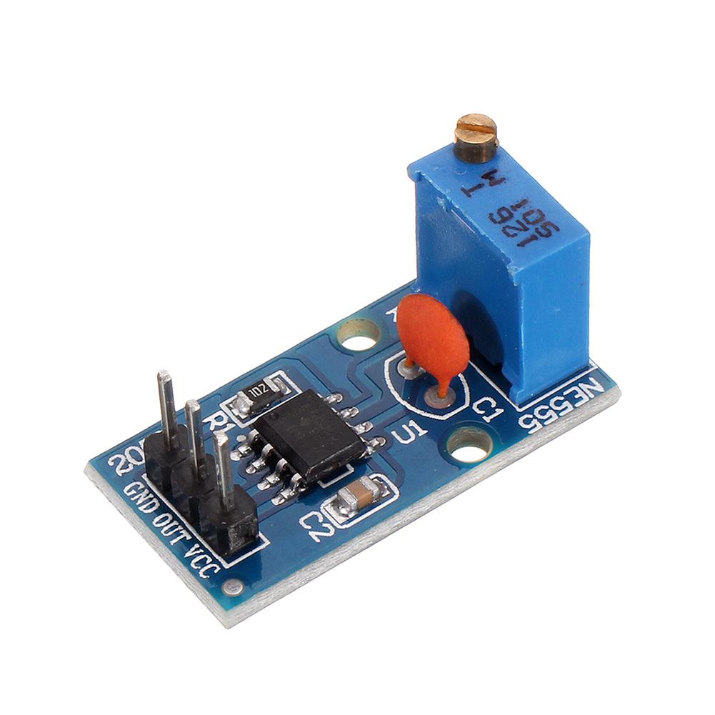
50pcs NE555 Adjustable Frequency Pulse Generator Module Smart Car
$54.46Generator ModuleAdd to cartFeatures1. NE555 chip onboard2. A single channel output, the output duty cycle square wave is about fifty percent3. Onboard adjustable resistance, resistance can be controlled to adjust the output frequency4. Working voltage:5 – 12V 5. Board size:29 (mm) x12 (mm)Package Included50 x NE555 Adjustable Frequency Pulse Generator Module
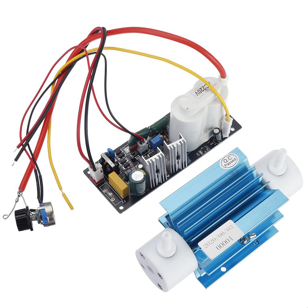
110V 5g Silica Tube Ozone Generator Module Ozone Output Adjustable Open Power Pack with Accessory
$74.34Generator ModuleAdd to cartSpecificationsInput Voltage:AC110VOzone tube dimension/ Weight:135x52x53mm / 0.3kgPower Pack dimension/Weight:152x72x68mm0.6kgPower consumption:3-40WCooling Style:air coolingAccessory:silicone tube 2 meter (6*8mm, since the ozone generator gas nozzle is 7mm), air stone 2 pcs (1 round and 1cylinder), air pump 5L/min 1pc. Ozone yield changes with the input gas flowFunction1. Sterilization:destroy variety of bacteria & viruse efficiently without secondary pollution.2. Detoxification:effectively …
ADF4351 Signal Source VFO Variable-Frequency Oscillator Signal Generator 35MHz to 4000MHz Digital LCD Display USB DIY Tools
$45.91Generator ModuleAdd to cartFeaturesSimple RF signal source signal generator.Core components:avr mega8 microcontroller, cost-effective single-chip microcomputer, is commonly used m16 low version, peripheral ADC has a 2.56V regulator source, this is not available in other mid-range microcontrollers.Adf4351, the traditional VCO+PLL+6 series high-speed bistable circuit (except 2 circuits, D trigger).35-2200MHz is obtained by frequency division. After being shaped, the amplitude …
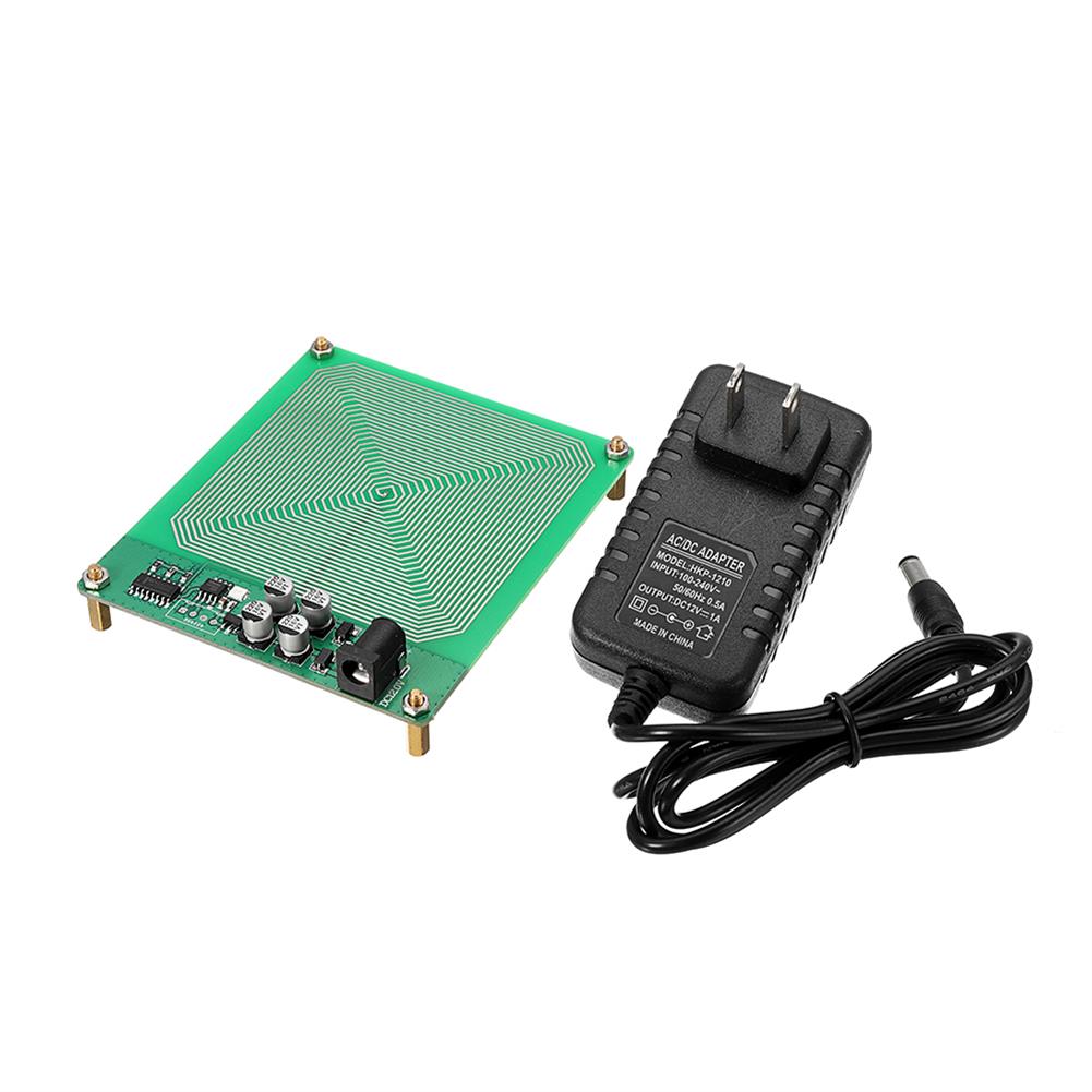
FM783 Schumann Wave Module Extremely Low Frequency Pulse Generator
$50.29Generator ModuleAdd to cartProduct technical parametersName:Schuhmann wave pole low frequency pulse generatorRated voltage:DC 12VRated current:1.5AApplicable voltage:100V-240V global general-purposeProduct accessories:wooden box finished products directly plug in electricity, standard 12V DC power supply.Know Schuhmann waveIn 1952, Schuhmann pointed out that the earth and the ionosphere could form a resonant cavity. There was a special resonant frequency in the cavity, which …
FM783 Schumann Wave Module Extremely Low Frequency Pulse GeneratorRead More

Customers Also Viewed
2000PCS 1 Pin Header Connector Housing for Dupont Wire Jumper Compact
$31.63Electronic Accessories & SuppliesAdd to cartFeatures2.54mm Single-row strip Dupont Wire Jumper.Professional and compact, light weight.Material:PlasticSize:14 x 2.5mm/ 0.55 x 0.1inch (L x W)Color:BlackPackage includes2000 x 1Pin Header Connector
HIFI 2.0 Stereo bluetooth 5.0 Lossless Decoding 27W*2 Digital Class D Car Speaker Audio Power Amplifier Board
$8.73Amplifier BoardAdd to cartDescriptionAVN-302 is a low EMI, no filter, Class D Bluetooth audio decoding power amplifier, with an internal protection mechanism for overcurrent, undervoltage, short circuit and overheating automatic shutdown.SpecificationModel:AVN-302Power:7.4V-14.4VSize:55*50mmOutput power:27W*2Boot instructions1. Insert the U disk, load the file (reading completed) automatically enter the playback, the red indicator flashes2. In the playback state, short press the ‘P/P’ …
CJMCU-1286 PIC16F1823 Microcontroller Development Board
$8.73Motherboard & Development BoardAdd to cartDescriptionCJMCU-1286 is a PIC microcontroller minimum system, running stability and high reliability,internal resources are relatively small, so the microcontroller is simple and convenient to use.The operating voltage is 1.8V – 5.5V.Package included1 x CJMCU-1286 PIC16F1823 Microcontroller Development Board
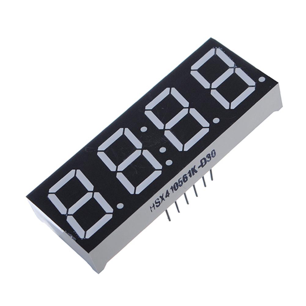
4Pcs 7-Segment 0.56 inch 4 Digit 12 Pins Red LED Display
$8.38Display ScreenAdd to cart4Pcs 7-Segment 0.56 Inch 4 Digit 12 Pins Red LED DisplayDescriptionWith time displayCommon anodePin Number:12 pinsDigit Number:4 digitsDigit Height:0.56 inch / 1.4 cmSize (L x W ):2 x 0.75 inch / 5 x 1.9 cmColor:RedPackage included4 x 0.56’inch 4 Digit LED Display
3pcs M5Stack StickC Pro to Plus Hat Prototype Diy Protoboard Breadboard PCB Universal Board
$31.71Expansion Board & ShieldAdd to cartProduct FeaturesHole Size:0.039inch 1mm (CNC Drilled)Hole Pitch:0.1 in – (2.54 mm)Entire Hole Quantity:168 HolesPackage Included3 x PRO TO PLUS HAT3 x 8 pin header ( 90° )


Reviews
There are no reviews yet.