


5pcs ESP-12F AC/DC Power Supply ESP8266 AC90-250V/DC7-12V/USB5V WIFI Single Relay Module Development Board
$70.21
Shipping:Standard Shipping about 10-25 business days
Secure Payment:Paypal,VISA,MasterCard
Size Conversion
Inches
Centimeters
Please according to your own measurements to choose your suitable size. The tags inside the items will show in our Asian (Type) size.
Feature
1. On-board mature and stable -12F WIFI module, large capacity 4M Byte Flash
2. The I / O port and UART program download port of the WiFi module are all exported, which is convenient for secondary development.
3. On-board AC-DC switching power supply module, power supply mode supports AC90-250V / DC7-12V / USB5V
4. On-board WIFI module RST reset button
5. -12F supports the use of development tools such as Eclipse / for Arduino IDE, and provides reference programs under the for Arduino development environment.
6. One 5V relay on board, output switching signal, suitable for controlling load with working voltage within AC250V / DC30V
7. Onboard power indicator, 1 programmable LED and relay indicator
Function
1. L, N:AC90-250V power supply
2. AC90-250V to DC5V switching power supply (Do not touch here directly with your hand when using AC power supply !!!)
3. VCC, GND:DC7-12V power supply;
4. USB:DC5V USB power supply;
Note:AC90-250V, DC7-12V, DC5VUSB can be selected as one of the three power supply methods.
5. 6X6mm button:8266 reset button;
6. UART program download port:GND, RX, TX, 5V of 8266 are connected to GND, TX, RX, 5V of the external TTL serial module rectively. IO0 must be connected to GND when downloading, and then disconnected connection;
7. GPIO pin out port;
8. Relay output
Normally closed end, the relay is short-circuited to COM before pull-in, and suspended after pull-in;
COM:public end;
NO:Normally open, the relay is suspended before the pull-in, and shorted to COM after the pull-in.
9. Power indication LED;
10. Programmable LED;
11. Relay Indication LED:Lights up during pull-in.
Introduction to GPIO terminal
Number:Name:Function:Number:Name:Function
1:GND:Power ground:13:IO10:GPIO10
2:Relay:The relay drive port is driven by IO5 by default. If you want to use other I / O to drive the relay, you can remove R14, and then connect the I / 0 of the drive relay to this Relay pin:14:MISO:Slave output input
3:IO2:GPIO2; UART1_TXD:15:IO13:GPIO13; HSPI_MOSI; UART0_CTS
4:IO4:GPIO4:16:IO14:GPI014; HSPI_CLK
5:RX:UART0_RXD; GPIO3:17:ADC:A / D conversion result. Input voltage 0 ~ 1V, value:0 ~ 1024
6:3V3:3.3V power supply:18:3V3:3.3V power supply
7:SCLK:clock:19:MOSI:output Slave input
8:IO15:GPIO15; MTD0; HSPICS; UART0_RTS:20:IO9:GPIO9
9:IO0:GPIO0:21:CS0:Chip Select
10:IO5:GPIO5:22:IO12:GPIO12; HSPI_MIS0
11:TX:UARTO_TXD; GPIO1:23:IO16:GPIO 16
12:5V:5V power supply:24:GND:Power ground
Package includes
5 x Development Board
| Weight | 0.2 kg |
|---|
Related products
LILYGO TTGO T-Call V1.3 V1.4 ESP32 Wireless Module GPRS Antenna SIM Card SIM800L Board
$32.39Smart ModuleAdd to cartVersion InformationCN warehouse:1.4VUSA, UK warehouse:1.3VFeatureHardware SpecificationsChipset:ESPRESSIF-ESP32 240MHz Xtensa dual-core 32-bit LX6 microprocessorFLASH:QSPI flash 4MB / PSRAM 8MBSRAM:520 kB SRAMButton:ResetUSB to TTL:CP2104Modular interface:UART, SPI, SDIO, I2C, LED PWM, TV PWM, I2S, IRGPIO, capacitor touch sensor, ADC, DACLNA pre-amplifierOn-board clock:40MHz crystal oscillator Working voltage:2.7V-3.6VWorking current:About 70mASleep current:About 300uASIM card:Only supports Nano SIM cardWorking temperature range:-40→ ~ +85→Size&Weight:78.83mm*28.92mm*8.06mm(11.77g)Power …
LILYGO TTGO T-Call V1.3 V1.4 ESP32 Wireless Module GPRS Antenna SIM Card SIM800L BoardRead More
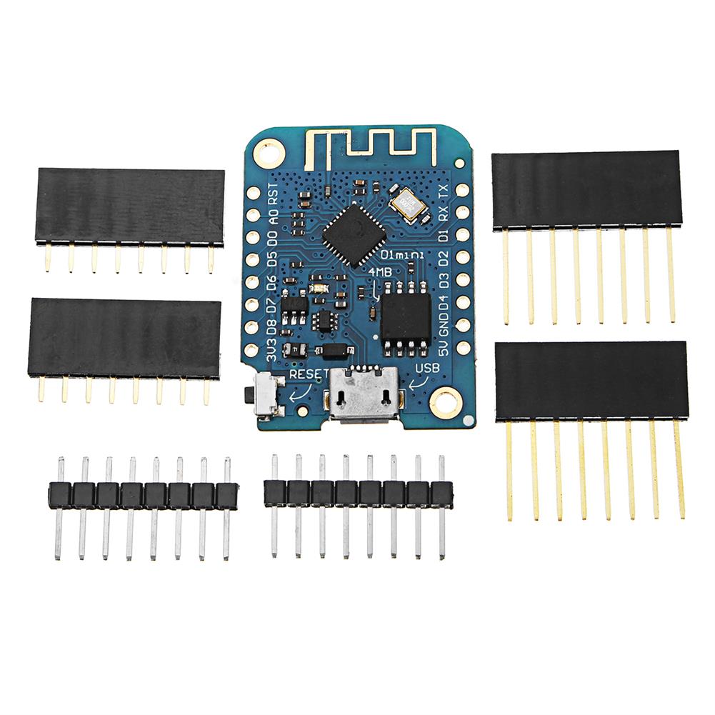
3pcs D1 Mini V3.0.0 WIFI internet of Things Development Board Based ESP8266 4MB Geekcreit for Arduino – products that work with official Arduino boards
$25.11Smart ModuleAdd to cartWhat’s new about V3.0.0Optimize the circuitAdd Deep-Sleep jumper.Default firmware:lastest MicroPython ESP8266 firmware.Features11 digital input/output pins, all pins have interrupt/pwm/I2C/one-wire supported(except D0)1 analog input(3.2V max input)a Micro USB connectionCompatible with MicroPython, , Nodemculots of ShieldsPackage included3 x D1 mini V3.0.06 x Normal pin6 x Long female pin6 x Short female pin
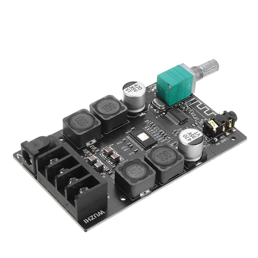
3pcs M28 bluetooth 4.2 Audio Receiver Module with 3.5mm Audio interface Lossless Car Speaker Headphone Amplifier Board Wireless Refit
$15.84Smart ModuleAdd to cartFor different needs of customers, we offer 3 versions for you to choose fromFunction / Model:M18 (Product ID:1476791):M28 (this item):M38 (Product ID:1486746)Micro power supply:*:√:√Audio headphone jack:*:√:*Built-in amplifier:*:*:√(5W+5W)Lithium battery powered:√:√:√Support USB sound card, free drive:*:*:√Volume memory/adjustment:√:*:*MUTE mute interface:√:*:*Button extension:√:*:*Bluetooth version:bluetooch V4.2Support Bluetooth protocol:HFPV1.7, A2DPV1.2, AVRCPV1.5, AVCTPV1.2, AVDTPV1.2Format support:Support WAV/WMA/FLAC/APE/MP3 lossless decoding, stereo two-channel outputOperating Voltage:5V/3.7V-4.2VBroadcast status …
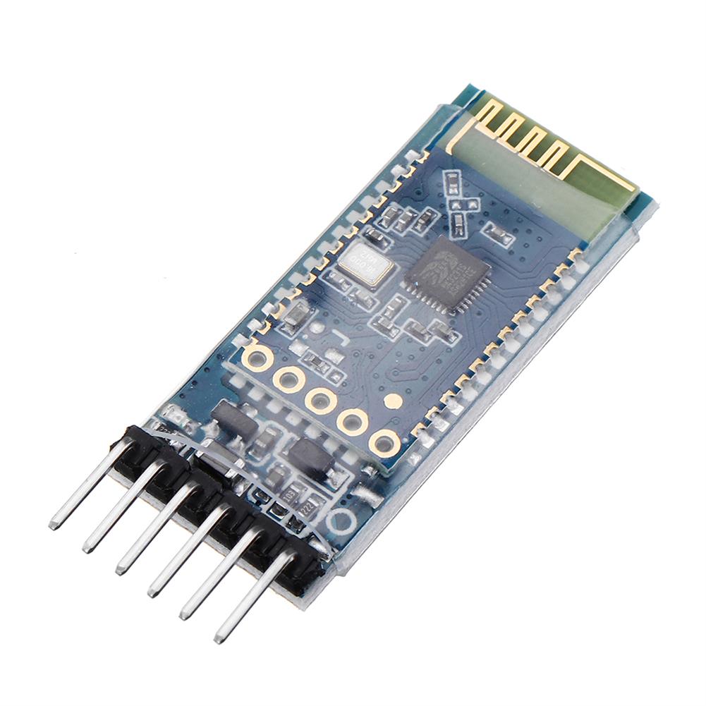
JDY-31 DC 3.6-6V bluetooth 2.0/3.0 Module SPP Protocol Android Compatible with HC-05/06 JDY-30
$6.55Smart ModuleAdd to cartDetails:Click here to openProduct introductionJDY-31 Bluetooth is based on Bluetooth 3.0 SPP design, which can support Windows, Linux, android data transmission, working frequency 2.4GHZ, modulation mode GFSK, maximum transmission power 8db, maximum transmission distance 30 meters, support users to modify device name through AT command The baud rate and other instructions are convenient and quick …


Customers Also Viewed
3pcs 2x50W TPA3116 AUX+Bluetooth 5.0 HIFI High Power Digital Amplifier Stereo Board AMP Amplificador Home theater without Shell
$54.90Amplifier BoardAdd to cartSpecificationsAudio input:AUX+bluetoothWork voltage:9-24 DCPower:2*50WCooling fin:LargeSpeaker:4-8Ω;30-200WProtection:Overvoltage,undervoltageSize:84*52*24mmFeatures1. This product is full of materials, featuring high performance and high performance price, especially for HIFI music power amplifier with high power and high fidelity.2. TPA3116D2 is a type D amplifier IC launched by TI company, which has very high index parameters.The maximum modulation frequency is 1.2MHZ, and the high …
5PCS USB To TTL Debug Serial Port Cable for Raspberry Pi 3B 2B / COM Port
$20.44Raspberry Pi & Orange PiAdd to cartMore info and driver, please !!!Supports WIN XP/WIN7/ WIN8/ WIN10Reference to WIN10, you can !!!NoteNo driver on raspberry pi 3 model bRaspberry Pi main board is not included!Package included5x USB To TTL Debug Serial Port Cable For Raspberry Pi / COM Port
DIY LED Light Kit ONLY for LEGO 60197 Passenger Train Building Block Bricks Lighting
$32.79DIY Electronic KitsAdd to cartSpecificationInterface:USBColor:As the picture shownThe product is just a light kit, not included the model!!!FitmentONLY For LEGO 60197 Passenger Train Building Block Bricks ToyFeaturesEasy to install.LED powered by USB.Make your model more cool.Package Included1 x LED Light Kit(Model Not Included)
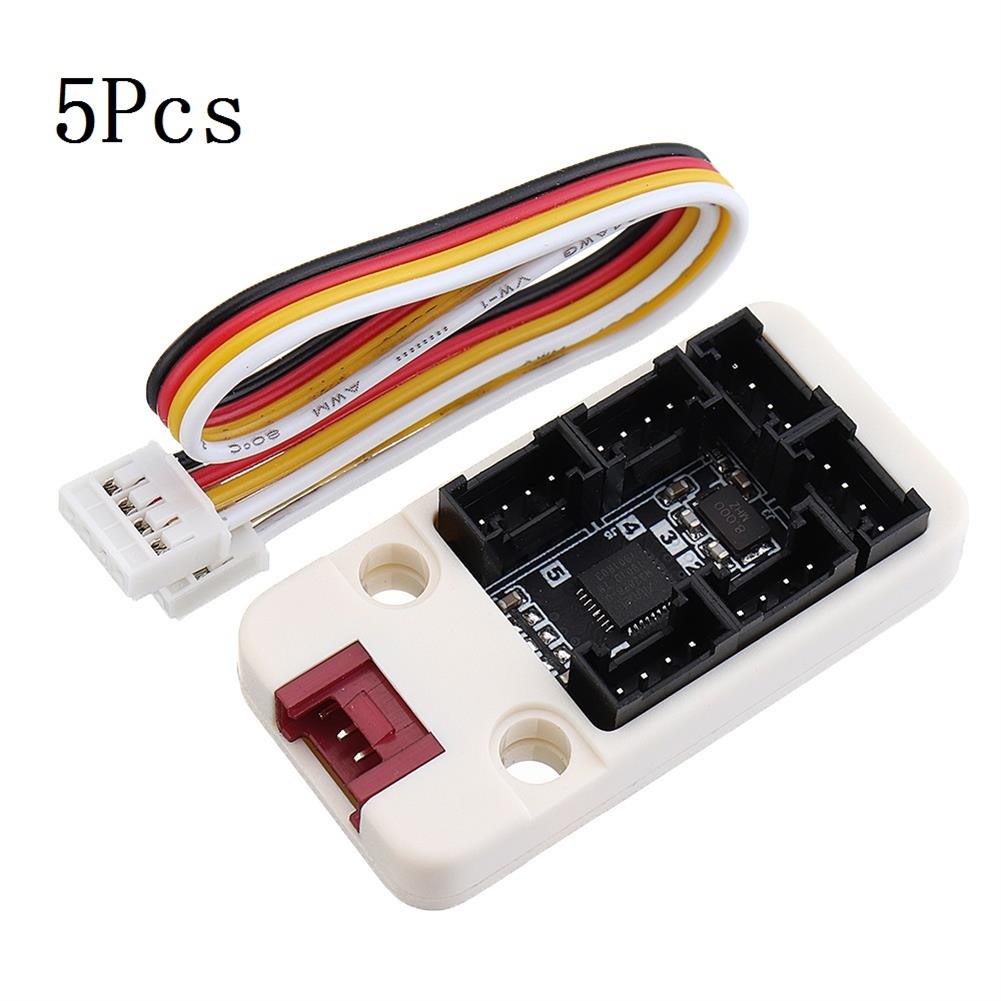
5Pcs M5Stack I/O Hub 1 to 6 Expansion Board Grove I/O interface for Blockly Development IoT MEGA328 Module for Arduino
$75.21Converter BoardAdd to cartDescriptionPbHUB, is a expander for singel-bus GROVE PORTB(Black port on M5GO Base). 1-to-6. PortB can be used as GPIO and analog in two data lines connected to GPIO36 and GPIO26 on ESP32. Same as PaHUB, it provides a solution for mutiple device control by PORTB. With PbHUB each of the IO can be configurated to …
10Pcs Green LED Power Symbol Momentary Latching Switch LED Light Push Button SPST
$20.86Electronic Accessories & SuppliesAdd to cart10Pcs Green LED Power Symbol Momentary Latching Switch LED Light Push Button SPSTDecriptionLatching type:Push it– on, push it again — offLED color:GreenSize(H*D):1.4 x 1cm / 0.55inch x 0.39inch (approx)Quantity:10 pcsFunction:MomentaryLED light voltage:3.2VSwitch voltage:12VMaximum operating current:20mAWith led light, with power symbol, light touch switchEasy to use and installNote1. Please check the picture and part number carefully …
10Pcs Green LED Power Symbol Momentary Latching Switch LED Light Push Button SPSTRead More
100Pcs Red Heat Shrink Solder Sleeve Seal Wire Splice Butt Connector AWG 22-18GA
$72.89ConnectorsAdd to cartName:(100) Heat Shrink Solder Sleeve Seal Wire Splice Butt Connector AWG 22-18GA RedMaterial:Tinned CopperColor:RedShrinking Ratio:2:1Working temperature:-55℃~125℃Shrink temperature:80℃Solder melting temperature:138℃Complete solder melting temperature:160℃Cable cross-section:0.5mm-1.0 mmDiameter:3mm/0.12inch(appr.)FeaturesPlacement on Vehicle:Left, Right, Front, Rear.Solder and seal and with advanced waterproof function.Polyolefin tubing in outside and hot melt adhesive in inside.Can be ideal used in marine and automobile applications.Improve pullout strength, …
100Pcs Red Heat Shrink Solder Sleeve Seal Wire Splice Butt Connector AWG 22-18GARead More


Reviews
There are no reviews yet.