


Constant Voltage Constant Current Step Down Module with LED Display Battery Charging Board DC 5-36V
$19.67
Shipping:Standard Shipping about 10-25 business days
Secure Payment:Paypal,VISA,MasterCard
Features
1, On-board voltage, current and power meter. This module can be easily used without a multimeter, which is simpler and more intuitive.
2, On-board USB interface, can easily charge digital products. (Note:The USB output voltage is the same as the module output voltage. It is not a fixed 5V output. Please confirm before charging the USB device.)
3, High power, high efficiency, 5A, low ripple;
4, Three major functions
(1) Used as a normal step-down module with overcurrent protection capability;
(2) It is used as a charger for various voltage value lithium batteries, batteries, nickel-cadmium nickel-hydrogen batteries (battery packs), and used in solar panels, wind turbines, etc.;
(3) Used as a high power LED constant current driving module;
5, With constant voltage and constant current two modes, there are indicators to indicate which mode the module is currently in;
6. When used as a lithium battery charger, you can set the float voltage and the charge current. There are indicators to indicate whether it is charging is already full;
7, With current limit protection, even if the output is short circuit will not burn the module.
8, On-board voltage, ammeter can be self-calibrated, there will never be inaccurate problems!
Specifics
Input Voltage:DC 5V To 36V (digital tube correctly displays power supply above 6.7V)
Output Voltage:1.25-32V continuously adjustable (input voltage needs to be 1.5V higher than the output voltage)
Output Current:adjustable, up to 5A (recommended for use within 4.5A)
Output Power:up to 75W (recommended to use within 50W, please reduce power when using large differential pressure)
Working Temperature:-40~+85 degrees
Working Frequency:180KHz
Conversion Efficiency:up to 96%
Is Short Circuit Protection:Yes
Is Over Temperature Protection:Yes (automatically turn off the output after over temperature)
Input Reverse Connection Protection:None, (If necessary, please input a large current diode in the input string)
Installation Method:4 3mm silk
Wiring Method:Terminal block or soldering terminal, V-IN is input, V-OUT is output.
Application range
1. Use as a normal buck module with overcurrent protection
(1) Press the right button to adjust the digital meter to the [Display Output Voltage] interface, and adjust the “Constant Piezo Transistor” to make the output voltage reach the desired voltage value;
(2) Adjust the digital meter to the [display output current] interface, directly short the output end of the module (find a thick wire to short the output end), adjust the ‘constant current potentiometer’ to make the digital meter The current value reaches the preset overcurrent protection value; (for example, if the current value displayed by the onboard ammeter is 4A, then the maximum current of the module is limited to 4A, and the red indicator light is bright when the current reaches 4A)
(3) Connect the load and work.
2. Use as a battery charger
Modules without constant current function cannot be used to charge the battery. Because of the large voltage difference between the battery and the charger.
Causes the charging current to be too large, causing damage to the battery, so start charging the battery with constant current when charging
Automatically switch back to constant voltage charging to a certain extent.
(1) Determine the float voltage and charge current of the battery; (if the lithium battery parameter is 3.7V/2200mAh, then the float voltage is 4.2V, and the maximum charge current is 1C, ie 2200mA)
(2) Under no-load conditions, adjust the digital meter of the module to the [display output voltage] interface, and adjust the ‘constant piezoelectric positioner’ to make the output voltage reach the float voltage;
(3) Adjust the digital meter to the [display output current] interface, and directly short the output end of the module (find a thick wire to short the output end), then adjust the ‘constant current potentiometer’ to make the digital meter The current value reaches a preset charging current value;
(4) The charging lamp current defaults to 0.1 times the charging current; (the battery is gradually reduced during the charging process, gradually changing from constant current charging to constant voltage charging, if the charging current is set to 1A, then when When the charging current is less than 0.1A, the blue light is off, the green light is on, and the battery is charged.
(5) Connect the battery and charge it. (Steps 1, 2, 3, and 4 are:input terminal is connected to the power supply, and the output terminal is not connected to the battery.)
3. Use as LED constant current drive module
(1) Determine the operating current and maximum operating voltage at which you need to drive the LEDs;
(2) Under no-load conditions, adjust the digital meter to the [display output voltage] interface, adjust the ‘constant piezoelectric positioner’ to make the output voltage reach the LED working voltage;
(3) Adjust the digital meter to the [display output current] interface, and directly short the output end of the module (find a thick wire to short the output end), then adjust the ‘constant current potentiometer’ to make the digital meter The current value reaches a preset LED operating current;
(4) Connect the LED and test the machine.
(Steps 1, 2, and 3 are:input is connected to the power supply, and the output is not connected to the LED light)
Precautions
1. Do not share the input ground and output ground of the module. This will cause the module current sampling resistor to bypass, so that the module can not adjust the output current. It is easy to burn the module when the load is connected.
2. The output of the module has a current sampling resistor. After the load is connected, there will be a voltage drop of 0~0.2V, which is normal.
3. When the module output voltage cannot be adjusted, please turn the potentiometer counterclockwise for more than 10 turns, then use the module to adjust the voltage normally.
4. When the output exceeds 3A or 35W, please strengthen the heat dissipation!
Package Included
1 x Step Down Module
| Weight | 0.075 kg |
|---|
Related products
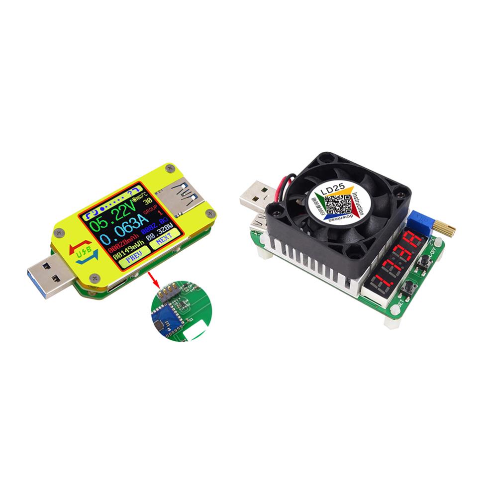
RIDEN UM34 USB 3.0 Type-C DC Voltmeter Ammeter Voltage Current Meter
$55.81Power Supply ModuleAdd to cartUM34 Technical ParameterProduct Model:UM34 Display screen:1.44 Inch color LCD displayVoltage measurement range:4-24.000V Voltage measurement resolution:0.01VCurrent measurement range:0-5.0000A Current measurement resolution:0.001ACapacity accumulation rannge:0-99999mAh Voltage measurement accuracy:±(0.2%+1digit)Energy sccumulation range:0-999.99Wh Current measurement accuracy:±(0.8%+3digits)Load impedance range:0.8Ω-9999.9Ω Time measurement range:0-99h59min59sTemperature range:-10→-100→/0-200 Temperature measurement error:±3→/±6Screen brightness setting:0-5 levels Auto screen off time:0-9minsVoltage graphing range:0-24.00V Current graphing range:-4.000ARefresh rate:2Hz Quick charge recognition …
RIDEN UM34 USB 3.0 Type-C DC Voltmeter Ammeter Voltage Current MeterRead More
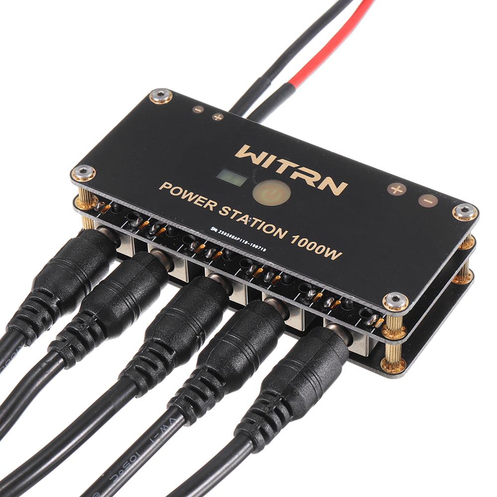
WITRN-PS500W 500W Charging Station PD DC Converter Charger Power Station Decoy Cable Lengh 25cm
$39.35Power Supply ModuleAdd to cartWITRN -PS1000W ID:1678499InputTYPE-C interface:Automatically deceives the highest voltage of PD, supports Emarker line, maximum 20V5A, 100WDC interface:5.5*2.5 DC interface, internal and external negative, input power is not recommended more than 300WXT30 interface:Supports up to 30A input, input power is recommended not to exceed 500WOutput5 * DC 5.5×2.5 interface outputsIndicator light:blue is the power indicator, red …
RIDEN UM34C for APP USB 3.0 Type-C DC Voltmeter Ammeter Voltage Current Meter
$65.11Power Supply ModuleAdd to cartUM34C Technical ParameterProduct Model:UM34C Display screen:1.44 Inch color LCD displayVoltage measurement range:4-24.000V Voltage measurement resolution:0.01VCurrent measurement range:0-5.0000A Current measurement resolution:0.001ACapacity accumulation rannge:0-99999mAh Voltage measurement accuracy:±(0.2%+1digit)Energy sccumulation range:0-999.99Wh Current measurement accuracy:±(0.8%+3digits)Load impedance range:0.8Ω-9999.9Ω Time measurement range:0-99h59min59sTemperature range:-10→-100→/0-200 Temperature measurement error:±3→/±6Screen brightness setting:0-5 levels Auto screen off time:0-9minsVoltage graphing range:0-24.00V Current graphing range:-4.000ARefresh rate:2Hz Quick charge recognition …
RIDEN UM34C for APP USB 3.0 Type-C DC Voltmeter Ammeter Voltage Current MeterRead More
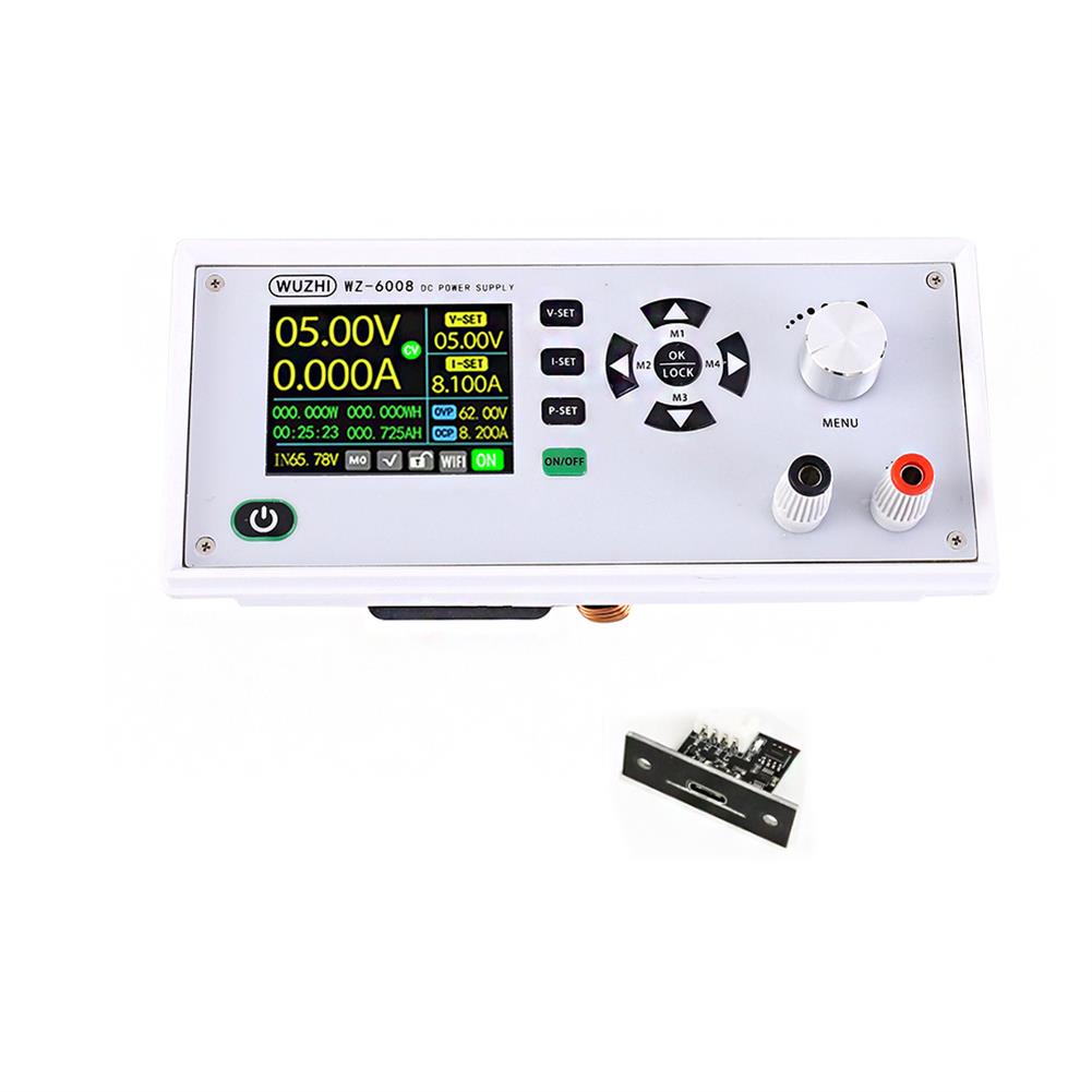
WZ-6008 USB Version DC-DC Voltage Current Step Down Power Supply Module Buck Voltage Converter Voltmeter 8A 480W with Programmable 2.4inch TFT LCD Display
$109.34Power Supply ModuleAdd to cartWZ-6008 Normal Version:1721320WZ-6008 USB Version:1721360WZ-6008 WIFI Version:1720641H08 Case Kit for WZ6008:1726866>>>Manual:Click here to openDescriptionThis is USB Version,USB communication version with host computer( docunment in manual)WZ-6008 is a multi-function Step Down Power Supply Module.Its main function is to output voltage as a constant voltage constant current source. It can be used to test the discharge time …

Customers Also Viewed
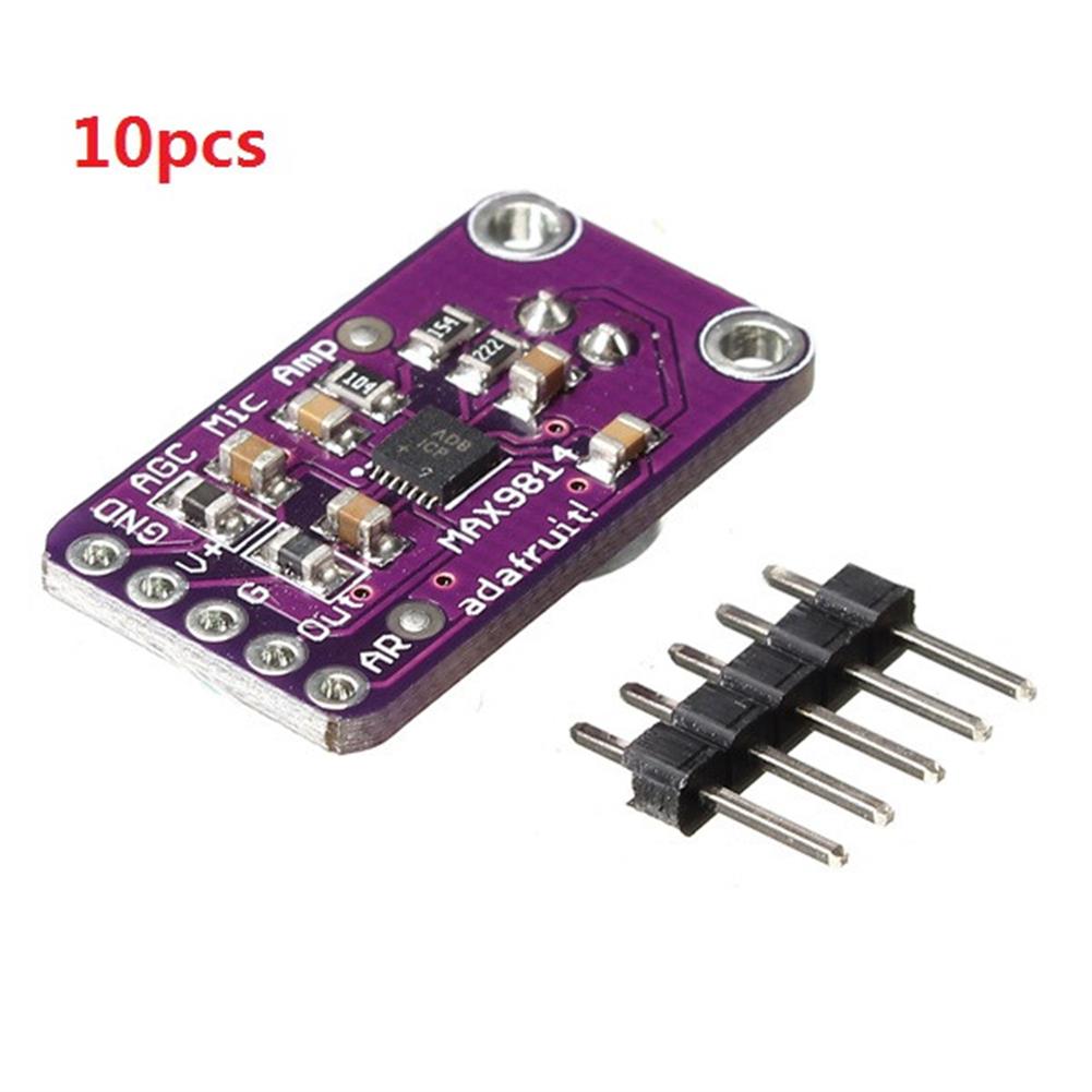
10pcs MAX9814 High Performance Microphone AGC Amplifier Module CMA-4544PF-W
$90.79Amplifier BoardAdd to cartSpecifications– Supply Voltage:2.7v-5.5v @ 3mA current– Output:2Vpp on 1.25V bias– Frequency Response:20Hz – 20KHz– Programmable Attack and Release Ratio– Automatic gain, selectable max from 40dB, 50dB or 60dB– Low Input-Referred Noise Density of 30nV/– Low THD:0.04% (typ)– Low Power Shutdown Mode– Built-in 2V low-noise microphone bias– -40°C ~ +85°C extended temperature rangePackage included10 x Microphone …
10pcs MAX9814 High Performance Microphone AGC Amplifier Module CMA-4544PF-WRead More
T-AMP 2 x 15W TA2024 Digital Audio Amplifier Board Mini AMP
$19.04Amplifier BoardAdd to cartFeature1. The power to more than 12V current 3A2. The speaker is best to use an impedance of 4 ohms, some of the high sensitivity3. For some signal level is relatively low tone, to add the preamplifier to play the effect4. Note the positive and negative can not be reversed, use the power supplyElectrical CharacteristicsIts …
T-AMP 2 x 15W TA2024 Digital Audio Amplifier Board Mini AMPRead More
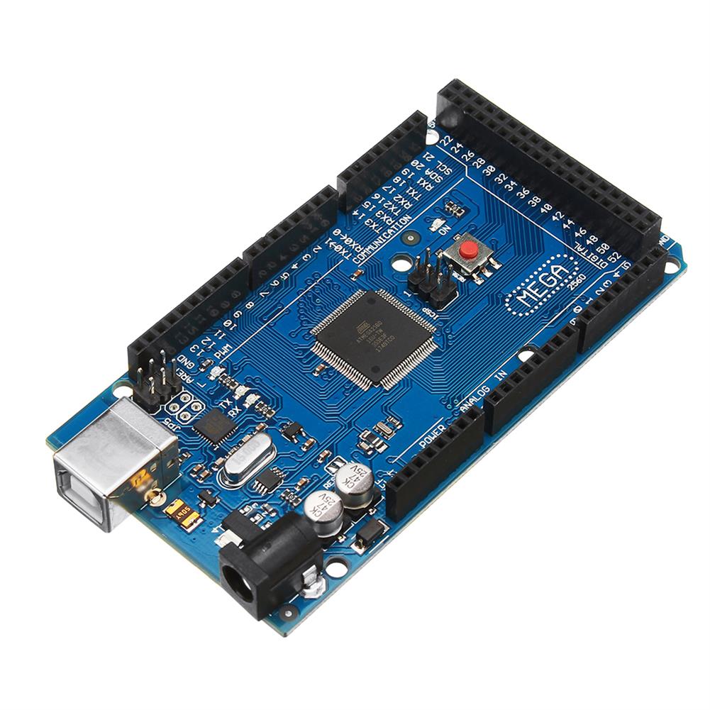
Mega 2560 R3 ATmega2560-16AU Control Module without USB Cable
$44.54Motherboard & Development BoardAdd to cartDescriptionThis is compatible R3 Mega2560 ATmega2560-16AU control board without USB cableMega is an ATmega2560 as core microcontroller development board itself has 54 groups digital I / O input / output terminal (14 groups do PWM outputs), 16 sets of simulation than the input side, group 4 UARTs (hardware serial ports), using the 16 MHz crystal …
Mega 2560 R3 ATmega2560-16AU Control Module without USB CableRead More
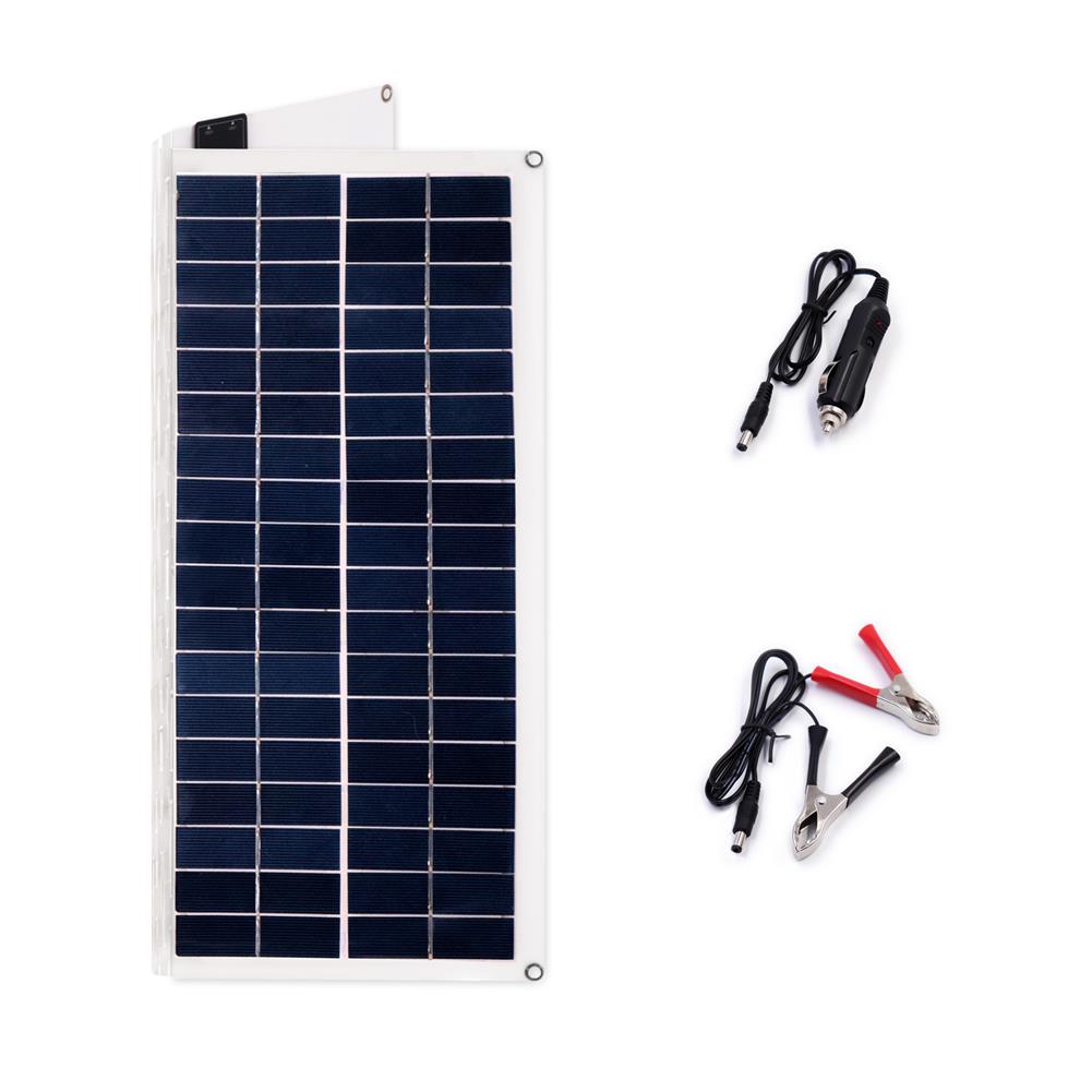
20W 420*380*3mm Folding PET Monocrystalline Silicon Solar Panel with Cable Dual USB
$93.62Smart Robot & Solar PanelAdd to cartSpecificationsMaximum Power(Pmax):20WOpen Circuit Voltage(Voc):18VMaximum Power Voltage(Vmp):12vMaximum Power Current(Imp):1.1AMaximum System Voltage(Imp):1000vOutput:USB 5V & DC 18VQuantity of cell:36Cell Effcience %:20%Output Tolerance:±10%Size:425*380*3mmStandard Test Conditions:Irradiance 1000w/m2Temoerature 25.C,AM=1.5Package Included1 x Solar panel with cable
5pcs 8Channel DC 5V RS485 Modbus RTU Control Module UART Relay Switch Board PLC
$45.10Relay ModuleAdd to cartDescriptions– Operating Voltage:DC 5V(5V Version)– Operating Current:10-15MA– inchopeninch inchcloseinch inchMomentaryinch inchSelf-lockinginch inchInterlockinch inchDelayinch 6 Commands– Two instruction-control mode:AT command and MODBUS command– Under the AT command ,the maximum delay is 9999 seconds– Under the MODBUS command ,the maximum delay is 255 seconds– AT commands can be made serial HyperTerminal (serial assistant) Enter;– MODBUS commands can …
5pcs 8Channel DC 5V RS485 Modbus RTU Control Module UART Relay Switch Board PLCRead More
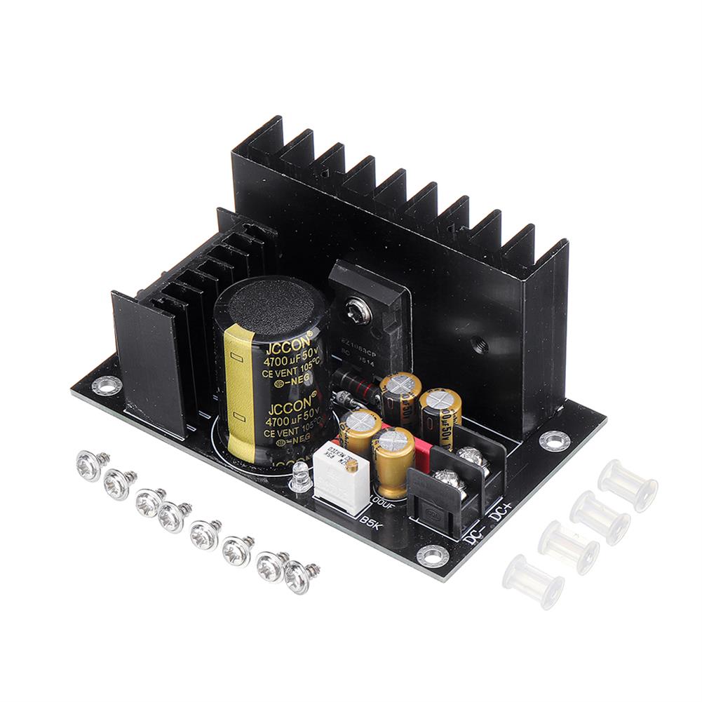
LT1083cp 7A AC 35V Rectifier Filter Power Supply Board DIY Home theater Sound Amplifier Voltage Regulator
$24.04Power Supply ModuleAdd to cartDescriptionLT1083CP feature description (emphasis):It is a linear step-down block. Although the voltage adjustment can be adjusted from 2.5V to 37V, it is recommended that the working differential pressure is within 10V, because the power consumption is proportional to the differential pressure, the greater the differential pressure, the more heat The larger the output current, the …


Reviews
There are no reviews yet.