


ZHIYU ZB206 12V Multi-Function Battery Capacity internal Resistance Tester 18650 Battery Tester
$45.91
Shipping:Standard Shipping about 10-25 business days
Secure Payment:Paypal,VISA,MasterCard
Feature
Supply voltage:DC 12V
Working current
Power port:5.5 x 2.1mm Power Port
Maximum battery input voltage:8.5V
Maximum error of discharge current:1%+2mA
Voltage measurement error:1%-3D
The maximum error of the overall measurement results:0.1-0.2A 2.5%, 0.3-0.5A 1.6%, 0.6-1.0A 1.2%, 1.1A-2.6A 1%
Circuit board size:118 x 74 x 43mm
Specifications
Quick Learning Instructions (Factory Default State)
1. Connect the positive pole and negative pole of a fully charged test battery to a blue connector BAT+ and BAT- with a short and thick connecting wire as far as possible! Power up the tester with DC 12V (power up 5V USB using micro USB power supply) and the tester is switched on showing preset current.
2. Press “S– Inch or “S++ Inch button to change the preset current from 0.1 – 2.6A; after the current change, press “SK Inch button to start test (if Err* shows, please refer to the instructions as follows); the tester automatically choose end voltage; “RUN Inch light lights up; LED display data, capacity Ah, energy Wh, voltage V, and current A take turns to show. After the test is finished, “RUN Inch light goes out and LED display showing Ah blinks rapidly with beeping at the same time.
3. Press “SK Inch button to make the tester stop blinking and beeping after you stop the test; check the capacity Ah, energy Wh, test process average process voltage V of the battery by pressing “S– Inch or “S++ Inch button; press “SK Inch button again and the tester returns to the starting-up state and the previous operation can be done again to test the next battery.
Warning:You must press the button again after the test to clear backup data; if not, the backup data will be saved all the time and even in power-off state of the tester!
Error code Err* meanings and treating methods
Err1:Overhigh battery voltage; please make sure that battery voltage is lower than 8.5V before test.
Err2:Battery voltage is too low (lower than setting end voltage); please confirm the battery voltage and set it again; battery reversal also shows Err2.
Err3:Battery cannot withstand current or wire is too thin or thick; please set down the current to do the test using thick and short wire with good electrode contact.
Err4:Damaged mosfet and normally speaking, bad transformation can lead to this problem; you can change the mosfet with model number P75NF75, ect..
Err5:Power overflow when power limit function is used (LPon); that means power in setting current is over limit.
Err6:Tester power supply voltage is out of range; please use the power supply with correct voltage!!
Note:Press any button to return to the initial state when it shows Err1 to Err5.
Full Function Detailed Instructions
1. Test Operation
1.1 Make sure that the tested battery is full charged.
1.2 Connect the positive pole and negative pole of a fully charged test battery to a blue connector BAT+ and BAT- safely and reliably with a short and thick connecting wire as far as possible! If it is 4-wire test mode, please connect the positive pole and negative pole of the holder’s voltage test wire to BV connector “+ Inch and “- Inch. Power up the tester with DC 12V (power up 5V USB using micro USB power supply); it is current setting state after the tester is normally started up; LED display shows setting current (e.g. 1.00A); press “S++ Inch or “S– Inch button to adjust setting current (long-press the button to quickly make the number go up and go down); when it is okay, press “SK Inch button.
1.3 Automatic Identification Mode (Factory Default Mode):Tester automatically identify the tested battery type and choose the optimal end voltage and discharge mode; it comes to tested work procedure when it shows the end voltage for 2 seconds.
Manual End Voltage Setting Mode:Manually set end voltage in the mode; press “S++ Inch or “S– Inch button to change battery end voltage (long-press the button to make the number go up and go down); P*.*u stands for continuous current test mode and b*.*u is the classical non-continuous current (open load voltage test) test mode (mainly used for counteracting wire resistance effect on 2-wire testing battery) and for example, P4.5u stands for continuous current test and end voltage is 4.5V. Setting range is b1.0u-b6.0u and P1.0u-P6.0u; please pay attention that when 4-wire test is started, non-continuous current test mode cannot be used! After setting end voltage, press “SK Inch button to do the test.
1.4 In test process preliminary stage, tester diagnoses the wire and battery; if there is something wrong with the wire or battery, the tester will not do the diagnosis showing fault diagnosis code Err* (please refer to the above part for error code Err* meanings and treating methods). After the diagnosis, the test is started; “RUN Inch light lights up; the discharge test starts; LED display data, 2 seconds A.h, 1 second W.h, 1 second battery voltage, and 1 second discharge current take turns to show with its indicator light being changed at the same time. After the test, “RUN Inch light goes out; LED display showing Ah blinks rapidly with beeping at the same time (set “bEon Inch).
1.5 Press “SK Inch button to make the tester stop blinking and beeping after you stop the test; check the capacity Ah, energy Wh, test process average voltage V of the battery by pressing “S– Inch or “S++ Inch button; press “SK Inch button again and all of the display data will be cleared to return to the initial current setting state.
Note:The maximum count data of the tester is 80.00Ah or 500.00Wh and if one appears, the test will be finished! If you want to test the battery over the count data limit, please record the current result and start the second test with the second result being added.
2. RES-V Test
Please use standard 4-wire test holder or Kelvin test holder! Make sure that the tester and the holder are well connected according to the above “1.2 Inch 4-wire test connecting wire’s requirements. Keep pressing “S– Inch button and power up the tester and the tester RES-V test function is enabled. Put the battery in the holder according to battery polarity and the tester shows battery internal resistance r*** (*** is internal resistance m, e.g. r065 is 65m and it does not show any value if it is overflow); at the same time press “SK Inch button and the V test is started showing battery voltage “*.**u Inch; press “SK Inch button to come to the internal resistance test…; for exiting RES-V test function, please shut off the tester.
RES test is DC pulse and its test result has deviation with AC test result; RES test can be used for quickly selecting battery.
Note:RES test cannot be used for testing dead battery.
3. Tester Working Parameter Setting
Keep pressing “SK Inch button and power up the tester and tester working parameter setting is started; press “S++ Inch or “S– Inch button to modify parameter; press “SK Inch button to come to the next and set the parameters in order as follows
I Use 2-wire test for “LJ 2 Inch (factory setting); 4-wire mode for “LJ 4 Inch.
II “Auon Inch battery automatic recognition function is enabled (factory setting); “AuoF Inch battery automatic recognition function is not enabled and after it, set end voltage manually.
III “bEon Inch buzzer is enabled (factory setting); “bEoF Inch buzzer if not enabled.
IV “LPon Inch power limit is enabled (factory setting); “LPoF Inch power limit is not enabled. Warning:More than 12W discharge is allowed for “LPoF Inch on condition that strengthening heat dissipation is the first thing and if not, mosfet may be burnt!
V “SF00 Inch “SF01 Inch…… “SF10 Inch, fan control enabled power numerical value:the current discharge power is over the latter two digits (W), fan control switch is on; “SF00 Inch means that once the discharge is started, fan control is on.
After the fifth setting is finished, press “SK Inch button and all of the setting parameters are saved and the tester is restarted to start work again.
4. Parameter and Result Being Automatically Saved and Backed up
4.1 When setting current and end voltage (automatic mode not enabled) and starting a test, current and end voltage parameter will be automatically saved; the parameter will be the default value next time.
4.2 When the tester is in discharge process and if it is suddenly powered off, tester will automatically save the current setting numerical value, working state, and test result; power up the tester with DC12V again and the tester will automatically restore discharge process.
4.3 When the tester blinks rapidly with beeping after the test being finished, the test result is backed up to avoid data loss before reading it; if you do not press button, the tester will not exit this state even if it is powered up again! If data is read after you press any button, backup will be cleared; after it, press “SK Inch button again or power it up again, it will come into initial current setting state.
“4.2 Inch and “4.3 Inch can make sure that a test is not affected by midway power cut! When portable power source is tested, the tester being powered up again comes into test finished state because portable power source with no load is being automatically turned off; if you need to continue to test, please record the current result by yourself and start a test again; please add the first test result and the second test result to get the final test result by yourself.
5. Test Process Midway Quit or Midway Current Modified
During discharge test process, press “S– Inch button to quit test and clear the result; if you need to midway modify discharge current or end voltage, press “S++ Inch button to quit test without clearing the result and after the setting, press “SK Inch button to continue the test.
6. How to Use the Fan
Tester has fan control design; connect the fan’s negative pole to LED display bottom right corner solder labeled with “F Inch and connect the fan’s positive pole to power supply’s positive pole to enable fan control function; please refer to “2 Inch for control parameter setting.
Note
a. “F- Inch maximum current is 0.2A and must not choose the fan over 0.2A!
b. If fan is installed for 5V version, only 5V fan is used because 12V output current of boost DC-DC is limited and it cannot load fan at the same time and the fan’s positive pole should be soldered on power supply connector boost DC-DC front near micro USB center’s rectangle pad (here input 5V).
Package included
1 x ZB206 battery capacity tester (including shell and fan)
| Weight | 0.157 kg |
|---|
Related products
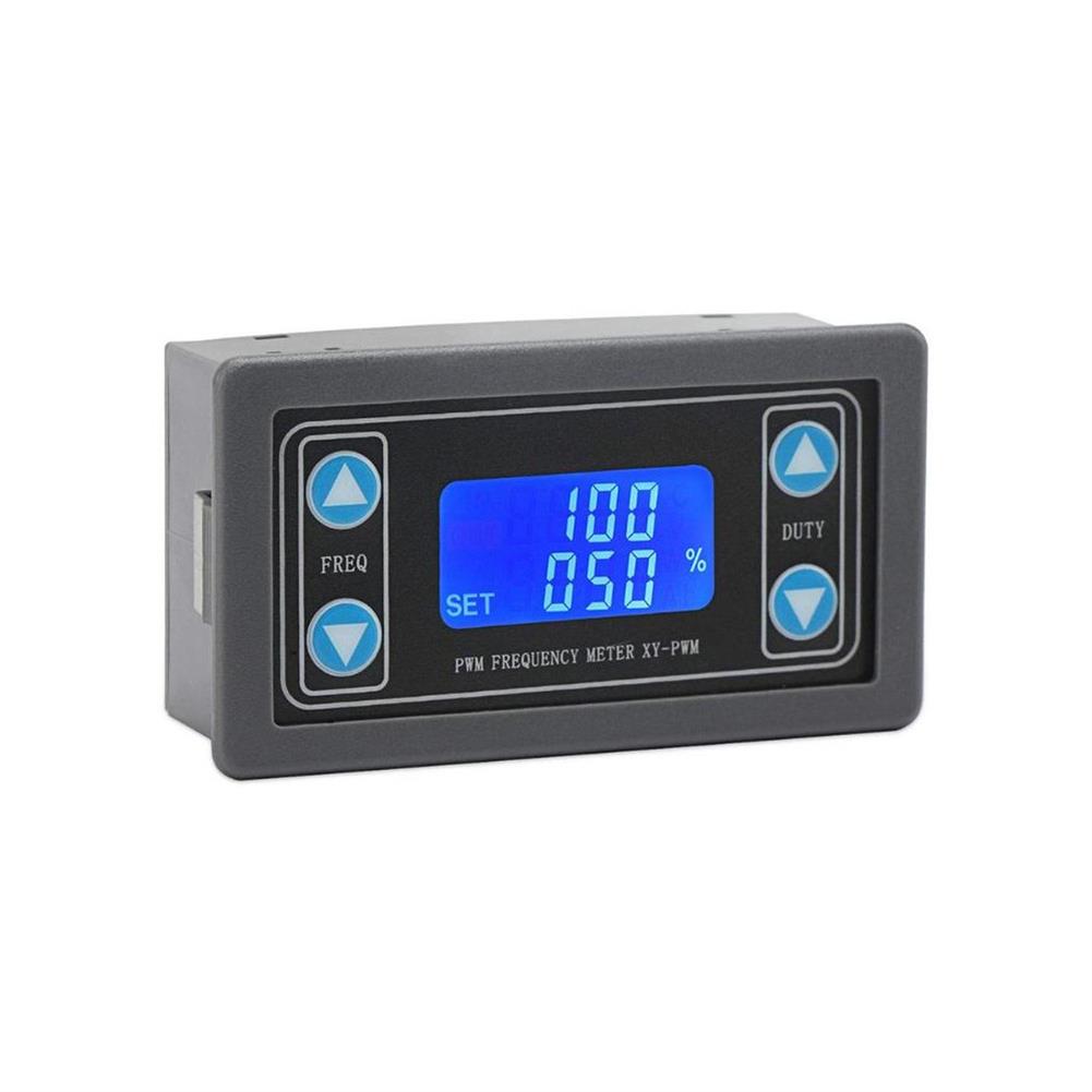
3pcs XY-PWM DC3.3-30V 1Hz~150KHz Digital Display Square Wave Rectangular Wave Pulse Signal Generator
$39.11Test & Measuring ModuleAdd to cartFunction1. Protective Shell2. LCD High Definition Display3. Support UART4. Supporting frequency adjustment5. Support duty cycle adjustment6. High accuracy detection7. Supporting POW ER-OFF memory function8. 0.1 Channel PWM Output9. Purpose:Device used as a signal source or excitation source in production practiceFeatureWorking voltage:3.3-30VFrequency ran ge:1Hz~150KHzFrequency accuracy:the accuracy in each range is about 2%Signal load capacity:output current can …
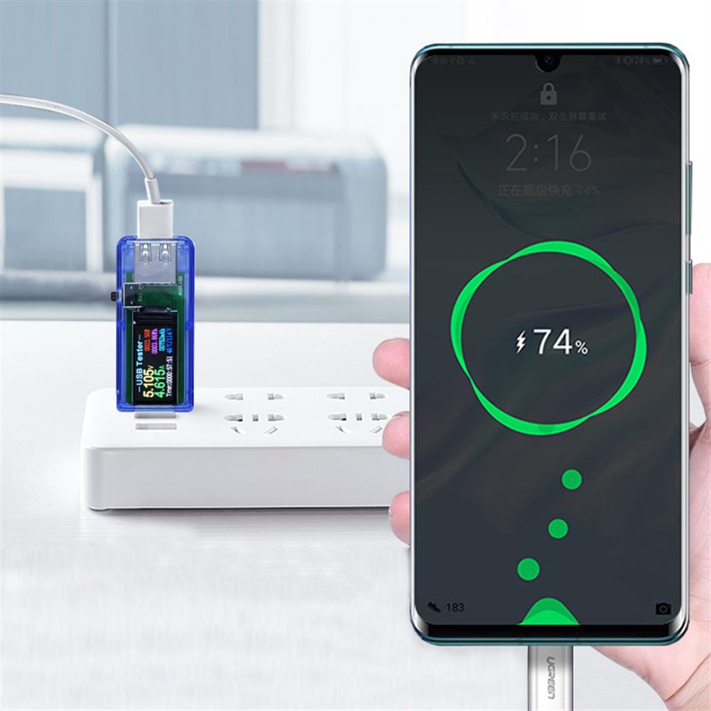
U96 USB Tester DC Digital Voltmeter Power Bank Charger indicator Voltage Current Meter Detector Blue
$18.58Test & Measuring ModuleAdd to cartU96 13 IN 1 Technical parametersVoltage measuring range:3.60V ~ 32.5 V Resolution precision:0.01 V Current measuring range:0.00A ~ 5.00 A Resolution precision:0.01 APower cumulative range:0 ~ 999999 WH Resolution precision:0.001 WhCapacity range:0 ~ 999999 mAH Resolution precision:0.001 AhTemperature:0 → ~ + 80 → Resolution precision:1 →D+ Voltage:0.000V ~ 2.999 V Resolution precision:0.001 VD- Voltage:0.000V ~ …
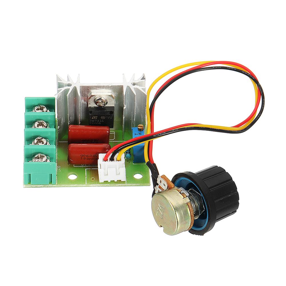
10pcs 2000W Thyristor Governor Motor 220V Regulating Dimming thermostat Module External Potentiometer Voltage Adjustable
$35.56Test & Measuring ModuleAdd to cartTips:This product needs to be connected to the load to adjust voltage, such as old-fashioned incandescent lamps or fans!FeatureUse voltage:AC 220VMaximum power:2000WVoltage regulation:AC 50-220VSpecification size:High temperature resistant FR-4 circuit board Circuit board size:about 36 x 48mmOuter size:48 x 60mm (knob direction) x 28mm (high)Control silicon withstand voltage up to 1200 volts / current 25A1.6mm thick …
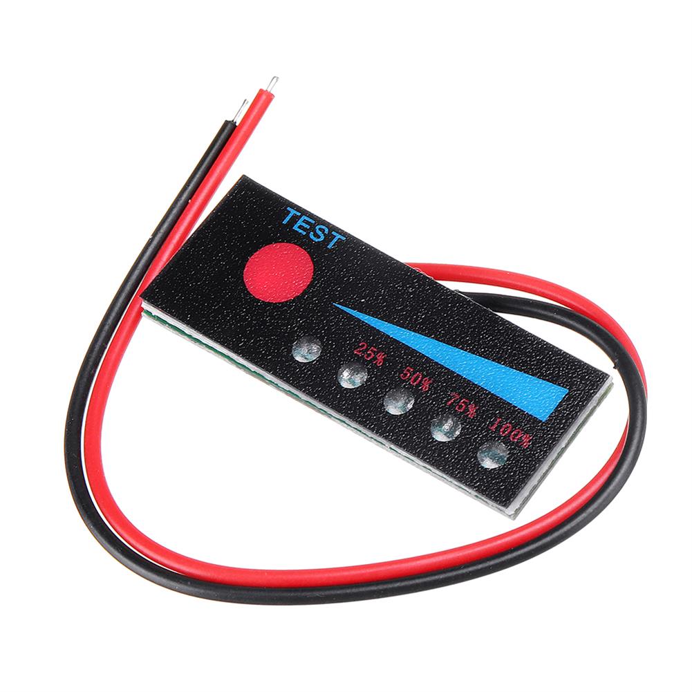
3.7V 1-7S Li-ion Lithium Battery 12-48V LiFePO4 Battery Power indicator Board 12V Car Lead Acid Battery Level Capacity Meter with Reverse Connection
$4.36Test & Measuring ModuleAdd to cartBattery 1S / Battery 2S / Battery 3S / Battery 4S / Battery 5S / Battery 6S / Battery 7S / Battery 12V / Battery 24V / Battery 36V / Battery 48V /
Customers Also Viewed
50Pcs KW12-3 Micro Limit Switch with Roller Lever Open/Close Switch 5A 125V
$16.52Electronic Accessories & SuppliesAdd to cartFeaturesOperating temperature:-40°C to 70°CRated voltage:AC 125V-250VPer weight:2gCurrent rating:5ASize:20 x 10 x 6mm (L X W X H)PCB Terminals Circuit BoardWith Roller Lever LimitWorking principleBy external mechanical force transmission elements (by pins, buttons, levers, rollers, etc.) will be used to force action on a reed, producing reed instantaneous action when action shifted to the critical point, …
50Pcs KW12-3 Micro Limit Switch with Roller Lever Open/Close Switch 5A 125VRead More
129Pcs/Set Silicone Casting Molds and Tools Jewelry Pendant Resin Mould DIY
$20.24Lab TubesAdd to cartFeatures-This set of making tool is especially designed for DIY expoxy resin crafts, including silicone mold,spoon,sequin,drill,nails and so on.-Different silicone molds have different shapes for you to choose,which may accurately match your various needs.-It is easy control with the reliable quanlity as well as the efficence. -The superior DIY tools for your craft works.SpecificationMaterials:Silicone,MetalType:Making ToolsQuantity:129pcs,one …
129Pcs/Set Silicone Casting Molds and Tools Jewelry Pendant Resin Mould DIYRead More
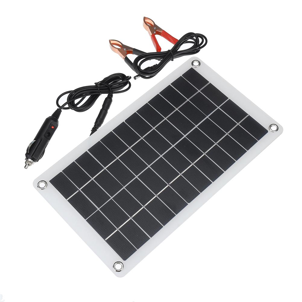
12V 7.5W Polysilicon Solar Panel Battery Charger Clip for Car RV Boat Outdoor
$60.74Solar PanelAdd to cartFeatures Lightweight and convenient to carry Long span life Easy to use Suitable for 12V battery, working temperature 0-60 ℃, reflow protectionSpecificationsMaterial:Grade A monocrystalline silicon solar panelPower:7.5W maxWorking voltage:12V (rechargeable 12V battery)Current:0-625MATemperature:-60 ° CSolar panel size:310 * 190mmPacking size:330 * 205 * 30mmNotice Make sure your battery is good and bad The level of the …
12V 7.5W Polysilicon Solar Panel Battery Charger Clip for Car RV Boat OutdoorRead More
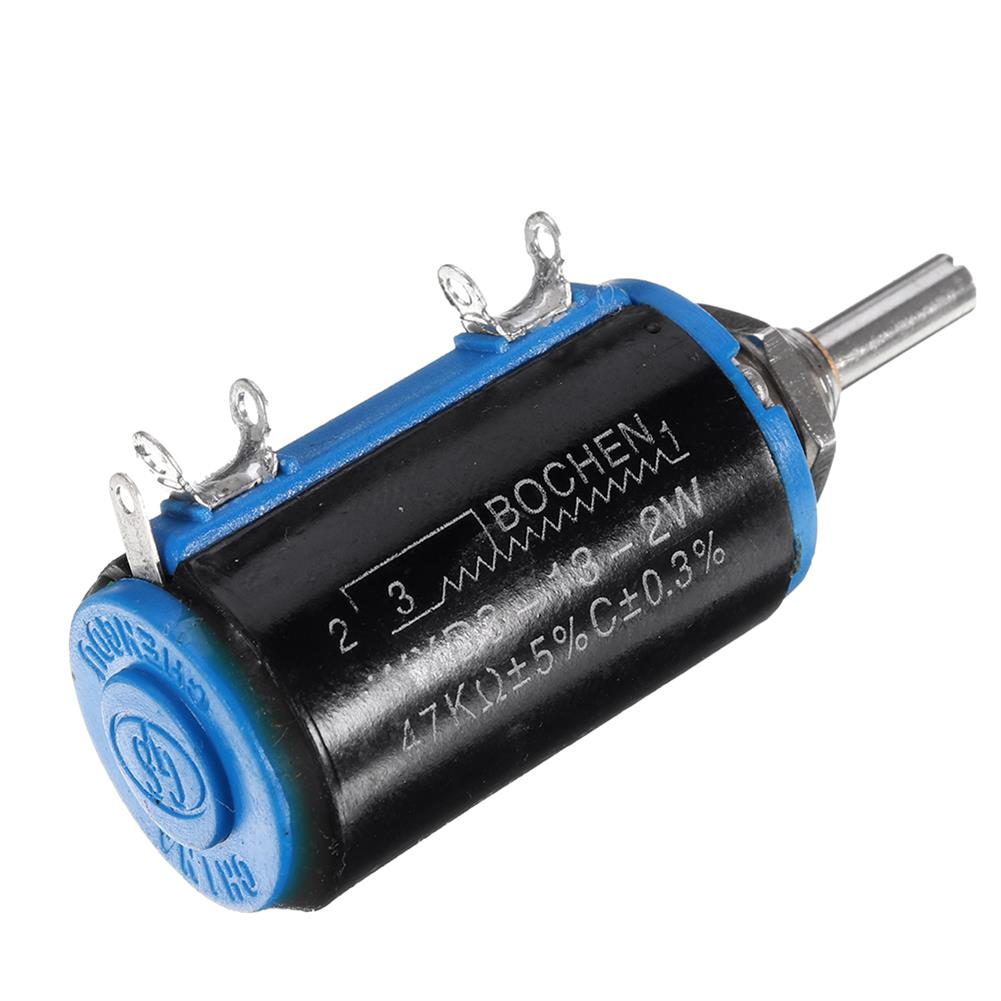
WXD3-13-2W Precision Potentiometer 470R 47K Ohm Wirewound Multi-Turn Potentiometer
$4.50Module ComponentsAdd to cartSpecificationsResistance range:47K┯Resistance tolerance:÷ 5%Rotation angle:3600 ÷ 20 Number of laps:10 lapsRated voltage:160VStarting torque:3.5 ~ 100mN.mRated power:2W (85 →) 0W (125 →)Linearity accuracy:÷ 0.3%Mechanical durability:10,000 weeksPackage included1 x Potentiometer
Mini Diving Equipment Scuba Diving Cylinder Scuba Oxygen Reserve Air Tank Set
$568.00Magnetic StirrerAdd to cartSpecificationsName:0.5L Portable Mini Oxygen Cylinder Air Oxygen Tank Breath DivingBreathing Oxygen CylinderCapacity:0.5LMaterial:Aviation aluminumOxygen cylinder weight:1040gOxygen cylinder dimension:φ6*35.5cm (2.4*14inch)Packing case size:65*10*38cm (25.6*4*15inch)Air capacity:3.0 Cu.Ft / 85 LittersMax. pressure:3000PSI / 200bar / 20MPaMax. dwell time underwater:10minNumber of underwater max. breathing:21 times(depending on individual lung capacity and depth of diving)High-pressure Inflatable PumpHigh pressure air pump material:stainless steelSize:62*26*3.6 cm(24.4*10*1.4inch)Barometer …
Mini Diving Equipment Scuba Diving Cylinder Scuba Oxygen Reserve Air Tank SetRead More
intelligent Dual LCD Pure Sine Wave Power inverter DC48V to AC220V 6000W for Home/Car/industry
$1,188.66InvertersAdd to cartSpecificationsType:Solar inverterOutput voltage waveform:Pure sine waveMatarial:Aluminum shellPower:6000WPeak Power:12000W (5000W Continous)Output voltage:220VInput voltage:48VInput DC low voltage protection:10V±0.5V DCInput DC high voltage protection:15.5V±0.5V DCOutput frequency:50Hz/60HzConversion rate:93% or moreSize:450x180x140mmWeight:8.9KG(Approx.)Appication:Home emergency/Industry/CarFeatures-High-precision circuit board.-Built-in intelligent control chip.-Dual LCD screen integration.-If the machine is abnormal, there will be an alarm.-Screw terminal. Pluggable plug, easy to replace the cable.-Universal socket, strong compatibility,most …
43.8V 1.6A Electric Bike Battery Charger for Scooter Power Supply Lithium Battery Charger
$46.56AC/DC AdaptersAdd to cartSpecificationsName:36V Lithium Battery Charger 43.8V 1.6AColor:BlackSize:155*90*50mm (6.1*3.5*2inch)Input:AC 100-240V 50-60HzOutput:DC 42V 0-2AInput plug:EU PlugOutput plug:1+, 3-Feature– This charger is suitable for all 36V lithium batteries.– Quick charge function.– Suitable for electric bicycle scooter.Package included1 x Lithium Battery Charger


Reviews
There are no reviews yet.