


ZHIYU ZB206 12V Multi-Function Battery Capacity internal Resistance Tester 18650 Battery Tester
$45.91
Shipping:Standard Shipping about 10-25 business days
Secure Payment:Paypal,VISA,MasterCard
Feature
Supply voltage:DC 12V
Working current
Power port:5.5 x 2.1mm Power Port
Maximum battery input voltage:8.5V
Maximum error of discharge current:1%+2mA
Voltage measurement error:1%-3D
The maximum error of the overall measurement results:0.1-0.2A 2.5%, 0.3-0.5A 1.6%, 0.6-1.0A 1.2%, 1.1A-2.6A 1%
Circuit board size:118 x 74 x 43mm
Specifications
Quick Learning Instructions (Factory Default State)
1. Connect the positive pole and negative pole of a fully charged test battery to a blue connector BAT+ and BAT- with a short and thick connecting wire as far as possible! Power up the tester with DC 12V (power up 5V USB using micro USB power supply) and the tester is switched on showing preset current.
2. Press “S– Inch or “S++ Inch button to change the preset current from 0.1 – 2.6A; after the current change, press “SK Inch button to start test (if Err* shows, please refer to the instructions as follows); the tester automatically choose end voltage; “RUN Inch light lights up; LED display data, capacity Ah, energy Wh, voltage V, and current A take turns to show. After the test is finished, “RUN Inch light goes out and LED display showing Ah blinks rapidly with beeping at the same time.
3. Press “SK Inch button to make the tester stop blinking and beeping after you stop the test; check the capacity Ah, energy Wh, test process average process voltage V of the battery by pressing “S– Inch or “S++ Inch button; press “SK Inch button again and the tester returns to the starting-up state and the previous operation can be done again to test the next battery.
Warning:You must press the button again after the test to clear backup data; if not, the backup data will be saved all the time and even in power-off state of the tester!
Error code Err* meanings and treating methods
Err1:Overhigh battery voltage; please make sure that battery voltage is lower than 8.5V before test.
Err2:Battery voltage is too low (lower than setting end voltage); please confirm the battery voltage and set it again; battery reversal also shows Err2.
Err3:Battery cannot withstand current or wire is too thin or thick; please set down the current to do the test using thick and short wire with good electrode contact.
Err4:Damaged mosfet and normally speaking, bad transformation can lead to this problem; you can change the mosfet with model number P75NF75, ect..
Err5:Power overflow when power limit function is used (LPon); that means power in setting current is over limit.
Err6:Tester power supply voltage is out of range; please use the power supply with correct voltage!!
Note:Press any button to return to the initial state when it shows Err1 to Err5.
Full Function Detailed Instructions
1. Test Operation
1.1 Make sure that the tested battery is full charged.
1.2 Connect the positive pole and negative pole of a fully charged test battery to a blue connector BAT+ and BAT- safely and reliably with a short and thick connecting wire as far as possible! If it is 4-wire test mode, please connect the positive pole and negative pole of the holder’s voltage test wire to BV connector “+ Inch and “- Inch. Power up the tester with DC 12V (power up 5V USB using micro USB power supply); it is current setting state after the tester is normally started up; LED display shows setting current (e.g. 1.00A); press “S++ Inch or “S– Inch button to adjust setting current (long-press the button to quickly make the number go up and go down); when it is okay, press “SK Inch button.
1.3 Automatic Identification Mode (Factory Default Mode):Tester automatically identify the tested battery type and choose the optimal end voltage and discharge mode; it comes to tested work procedure when it shows the end voltage for 2 seconds.
Manual End Voltage Setting Mode:Manually set end voltage in the mode; press “S++ Inch or “S– Inch button to change battery end voltage (long-press the button to make the number go up and go down); P*.*u stands for continuous current test mode and b*.*u is the classical non-continuous current (open load voltage test) test mode (mainly used for counteracting wire resistance effect on 2-wire testing battery) and for example, P4.5u stands for continuous current test and end voltage is 4.5V. Setting range is b1.0u-b6.0u and P1.0u-P6.0u; please pay attention that when 4-wire test is started, non-continuous current test mode cannot be used! After setting end voltage, press “SK Inch button to do the test.
1.4 In test process preliminary stage, tester diagnoses the wire and battery; if there is something wrong with the wire or battery, the tester will not do the diagnosis showing fault diagnosis code Err* (please refer to the above part for error code Err* meanings and treating methods). After the diagnosis, the test is started; “RUN Inch light lights up; the discharge test starts; LED display data, 2 seconds A.h, 1 second W.h, 1 second battery voltage, and 1 second discharge current take turns to show with its indicator light being changed at the same time. After the test, “RUN Inch light goes out; LED display showing Ah blinks rapidly with beeping at the same time (set “bEon Inch).
1.5 Press “SK Inch button to make the tester stop blinking and beeping after you stop the test; check the capacity Ah, energy Wh, test process average voltage V of the battery by pressing “S– Inch or “S++ Inch button; press “SK Inch button again and all of the display data will be cleared to return to the initial current setting state.
Note:The maximum count data of the tester is 80.00Ah or 500.00Wh and if one appears, the test will be finished! If you want to test the battery over the count data limit, please record the current result and start the second test with the second result being added.
2. RES-V Test
Please use standard 4-wire test holder or Kelvin test holder! Make sure that the tester and the holder are well connected according to the above “1.2 Inch 4-wire test connecting wire’s requirements. Keep pressing “S– Inch button and power up the tester and the tester RES-V test function is enabled. Put the battery in the holder according to battery polarity and the tester shows battery internal resistance r*** (*** is internal resistance m, e.g. r065 is 65m and it does not show any value if it is overflow); at the same time press “SK Inch button and the V test is started showing battery voltage “*.**u Inch; press “SK Inch button to come to the internal resistance test…; for exiting RES-V test function, please shut off the tester.
RES test is DC pulse and its test result has deviation with AC test result; RES test can be used for quickly selecting battery.
Note:RES test cannot be used for testing dead battery.
3. Tester Working Parameter Setting
Keep pressing “SK Inch button and power up the tester and tester working parameter setting is started; press “S++ Inch or “S– Inch button to modify parameter; press “SK Inch button to come to the next and set the parameters in order as follows
I Use 2-wire test for “LJ 2 Inch (factory setting); 4-wire mode for “LJ 4 Inch.
II “Auon Inch battery automatic recognition function is enabled (factory setting); “AuoF Inch battery automatic recognition function is not enabled and after it, set end voltage manually.
III “bEon Inch buzzer is enabled (factory setting); “bEoF Inch buzzer if not enabled.
IV “LPon Inch power limit is enabled (factory setting); “LPoF Inch power limit is not enabled. Warning:More than 12W discharge is allowed for “LPoF Inch on condition that strengthening heat dissipation is the first thing and if not, mosfet may be burnt!
V “SF00 Inch “SF01 Inch…… “SF10 Inch, fan control enabled power numerical value:the current discharge power is over the latter two digits (W), fan control switch is on; “SF00 Inch means that once the discharge is started, fan control is on.
After the fifth setting is finished, press “SK Inch button and all of the setting parameters are saved and the tester is restarted to start work again.
4. Parameter and Result Being Automatically Saved and Backed up
4.1 When setting current and end voltage (automatic mode not enabled) and starting a test, current and end voltage parameter will be automatically saved; the parameter will be the default value next time.
4.2 When the tester is in discharge process and if it is suddenly powered off, tester will automatically save the current setting numerical value, working state, and test result; power up the tester with DC12V again and the tester will automatically restore discharge process.
4.3 When the tester blinks rapidly with beeping after the test being finished, the test result is backed up to avoid data loss before reading it; if you do not press button, the tester will not exit this state even if it is powered up again! If data is read after you press any button, backup will be cleared; after it, press “SK Inch button again or power it up again, it will come into initial current setting state.
“4.2 Inch and “4.3 Inch can make sure that a test is not affected by midway power cut! When portable power source is tested, the tester being powered up again comes into test finished state because portable power source with no load is being automatically turned off; if you need to continue to test, please record the current result by yourself and start a test again; please add the first test result and the second test result to get the final test result by yourself.
5. Test Process Midway Quit or Midway Current Modified
During discharge test process, press “S– Inch button to quit test and clear the result; if you need to midway modify discharge current or end voltage, press “S++ Inch button to quit test without clearing the result and after the setting, press “SK Inch button to continue the test.
6. How to Use the Fan
Tester has fan control design; connect the fan’s negative pole to LED display bottom right corner solder labeled with “F Inch and connect the fan’s positive pole to power supply’s positive pole to enable fan control function; please refer to “2 Inch for control parameter setting.
Note
a. “F- Inch maximum current is 0.2A and must not choose the fan over 0.2A!
b. If fan is installed for 5V version, only 5V fan is used because 12V output current of boost DC-DC is limited and it cannot load fan at the same time and the fan’s positive pole should be soldered on power supply connector boost DC-DC front near micro USB center’s rectangle pad (here input 5V).
Package included
1 x ZB206 battery capacity tester (including shell and fan)
| Weight | 0.157 kg |
|---|
Related products
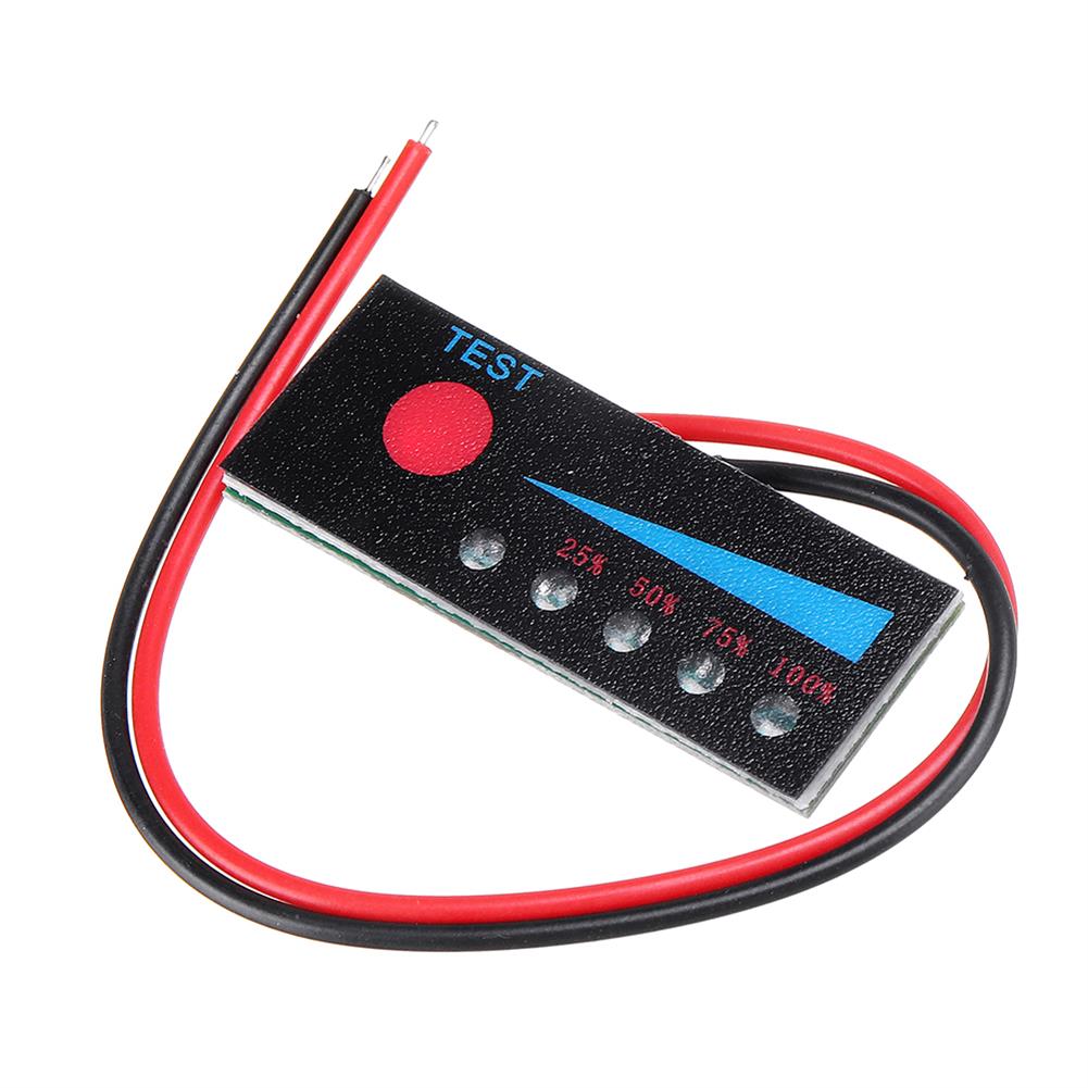
3.7V 1-7S Li-ion Lithium Battery 12-48V LiFePO4 Battery Power indicator Board 12V Car Lead Acid Battery Level Capacity Meter with Reverse Connection
$4.36Test & Measuring ModuleAdd to cartBattery 1S / Battery 2S / Battery 3S / Battery 4S / Battery 5S / Battery 6S / Battery 7S / Battery 12V / Battery 24V / Battery 36V / Battery 48V /
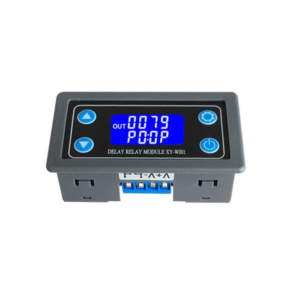
XY-WJ01 DC6-30V AC220 one Way Relay Module Trigger Delay Loop Timing Circuit Switch Electrical Equipment Supplies
$19.67Test & Measuring ModuleAdd to cartDescriptionMaterial:ABS + electronic componentsWorking voltage:6-30 V power supplyTrigger signal source:High-level touch (3.0V~24V), low-level trigger (0.0V~0.2V), switching quantity control (passive switch). 3:Output capacity:can control devices within 30v 10A or within 220v5AQuiescent current:15 mAWorking current:50 mAService life:More than 100,000 timesWorking temperature:-40~85 ° CWeight:45 gSize:7.1*3.9*2.5 cm (length, width and height)Package list:1*1pcsPrinciple:Time relayProtective features:SealedLiaison load:Low powerPower mode:DCFeatures1. With liquid …
Transistor Tester ESR Capacitance Meter Resistance inductance Measuring
$49.09Test & Measuring ModuleAdd to cartTransistor Tester ESR Capacitance Meter Resistance Inductance MeasuringSpecificationsVoltage:DC 9VCurrent:20mASize:80 x 53 x 20mmWire length:140mmDisplay size:57 x 37mmFunction introduction1. One key measure operation, time delay automatic power off. Turn off the current only 20mA, to support the operation of the battery.2. Automatic detection of PNP and NPN bipolar transistor, N, P channel JFET, MOSFET field effect …
Transistor Tester ESR Capacitance Meter Resistance inductance MeasuringRead More
3pcs 12 in 1 Transparent USB Tester DC Digital Voltmeter Amperemeter Voltagecurrent Meter Ammeter Detector Power Bank Charger indicator
$31.83Test & Measuring ModuleAdd to cartTechnical parametersVoltage measuring range:3.60V ~ 32.5 V Resolution precision:0.01 V Current measuring range:0.00A ~ 5.00 A Resolution precision:0.01 APower cumulative range:0 ~ 999999 WH Resolution precision:0.001 WhCapacity range:0 ~ 999999 mAH Resolution precision:0.001 AhTemperature:0 → ~ + 80 → Resolution precision:1 →D+ Voltage:0.000V ~ 2.999 V Resolution precision:0.001 VD- Voltage:0.000V ~ 2.999 V Resolution precision:0.001 …


Customers Also Viewed
7L 2 Hole Plastic Fuel Oil Gasoline Tank Air Heater Diesel Car Caravan Motorhome
$56.69Solar CollectorsAdd to cartFeature1. Made of thick and durable plastic.2. 7L large capacity, suitable for for cars / truck air diesel parking heater.3. Fuel level can be noticed by the plastic box.4. Easy to use.Specifications1. Name:7L Fuel Oil Gasoline Tank2. Model:D303633. Color:White & Blue4. Capacity:7L5. Size:approx.39x22x8cm(HxWxD)6. Material:Plastic & MetalPackage Included1 x Fuel Oil Gasoline Tank1 x Screw Kit
3Pcs XKC-Y25-T12V Non-Contact Liquid Level Switch Stick Type Durable Level Sensor Module
$40.82Sensor & Detector ModuleAdd to cartParameterInput voltage:(InVCC) DC 5 ~ 24 VCurrent consumption:5mAOutput voltage(High level):InVCCOutput voltage (Low level):0VOutput current:1 ~ 50mAResponse time:500mSWorking temperature:0 ~ 100 degreeInduction thickness (Sensitivity) Range:0 ~ 20mmCommunication:RS485Humidity:5% to 100%Material:ABSWaterproof:IP67Package included3 x XKC-Y25-T12V Non-Contact Liquid Level Switch
3pcs IB0505LS-1W DC-DC 5V to 5V Isolation Power Supply Module input 4.75-5.25V Output 5V
$17.04Power Supply ModuleAdd to cart>>>Manual:Click here to openOverviewThe IB_LD-1W & IB_LS-1W series are specifically designed for power applications in distributed power systems on the board that require isolation from the input supply. This product is suitable for1) The input power supply voltage changes ≤ ± 5%;2) The isolation voltage between input and output is required to be ≤1000VDC;3) High …
3pcs IB0505LS-1W DC-DC 5V to 5V Isolation Power Supply Module input 4.75-5.25V Output 5VRead More
20pcs DC-DC 12V 3A Power Supply Module Buck Regulator Module 24V 18V To 12V Fixed Output Step Down
$43.40Power Supply ModuleAdd to cartSpecificationsInput voltage:14 – 26VOutput voltage:12VOutput current:3A (Max), the current should be controlled within 0.8A for working long hoursConversion efficiency:96% (Max)Output rippleOperating temperature:-40→ – 85→Dimension:22.3 x 17 x 4.2mm (L x W x H)Package included20 x DC-DC 12V 3A Power Supply Module
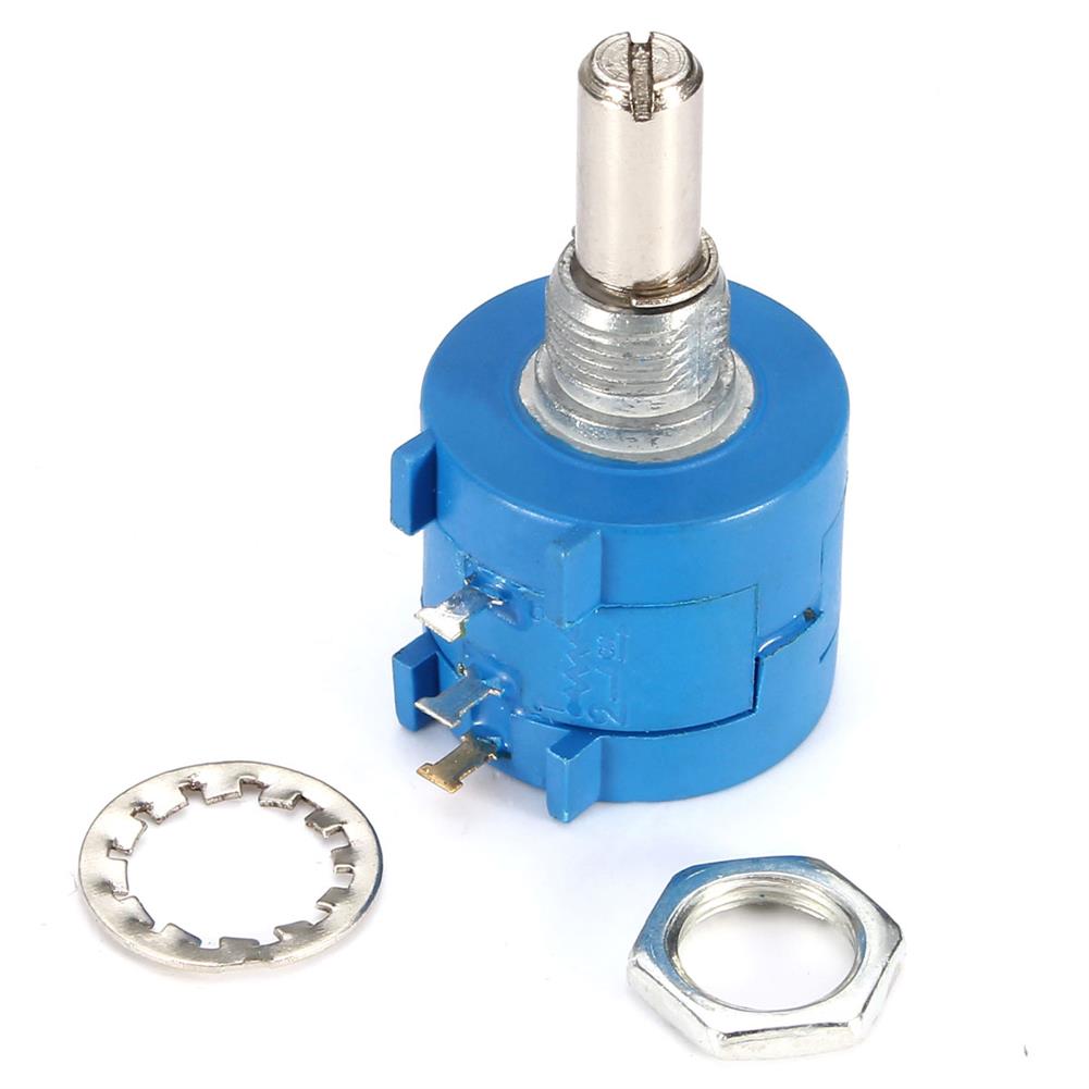
5Pcs 3590S-2-103L 10K Ohm BOURNS Rotary Wirewound Precision Potentiometer Pot 10 Turn
$21.55Electronic Accessories & SuppliesAdd to cart5Pcs 3590S-2-103L 10K Ohm BOURNS Rotary Wirewound Precision Potentiometer Pot 10 TurnDescription1. Color:As Pictures2. Resistance:10k ohm3. Resistance Tolerance:±5%.4. Power:2W5. Working Temperature:1→±125→6. Size:L x Dia / 40 x 20mm / 1.57 x 0.78inch7. Diameter of Shank:5mm/0.19inch8. Life Hour:1000 Hours9. Rotating Life:1,000,000 timesPackage include5 x Rotary Wirewound Precision Potentiometers
Transparent Acrylic Raspberry Pi 4B Case Box Support Cooling Fan instal
$9.18Raspberry Pi & Orange PiAdd to cartSize ConversionInchesCentimetersPlease according to your own measurements to choose your suitable size. The tags inside the items will show in our Asian (Type) size.Installation steps1. Press and hold the corner of the acrylic on the left, and talk about installing the acrylic on the left to the acrylic on the back.2. Attach the acrylic film …
Transparent Acrylic Raspberry Pi 4B Case Box Support Cooling Fan instalRead More
Solar Power inverter 6000W Peak DC 12V To AC 110V Modified Sine Wave Converter
$166.04InvertersAdd to cartFeatures– The inverter can convert DC12V to AC 110V.– Overload, over temperature, short circuit, low voltage, overvoltage protection.– Stable and precise output voltage.– Built-in cooling fan with low noise.– Comes with a car charger and a pair of alligator clip, convenient to use.– Perfect for TV, DVD player and other home appliances.SpecificationsColour BlackContinuous Output:3000 W …
Solar Power inverter 6000W Peak DC 12V To AC 110V Modified Sine Wave ConverterRead More
23*47CM Waterproof 80 LED Solar Street Light 120 Degree with Remote Control
$139.71Solar PanelAdd to cartFeatures– 80 LEDs High-brightness 3030 LED lamp beads, energy saving, even light, longer lasting.– Polycrystalline Solar Panel convert solar energy into electricity, more environmentally friendly.– ABS one-piece housing, high hardness, sealed and waterproof– Easy installation, maintenance-free dependable operation without the need for wiring or trench. Rustproof, waterproof aluminum heavy duty casing. – Please turn on …
23*47CM Waterproof 80 LED Solar Street Light 120 Degree with Remote ControlRead More


Reviews
There are no reviews yet.