


Subtraction Cycle Counter Circuit Kit 74LS192 Parts with Simulation Electronic DIY Training Kit
$12.15
Shipping:Standard Shipping about 10-25 business days
Secure Payment:Paypal,VISA,MasterCard
Feature
Electronic kit for French cycle counter circuit. This circuit is a digital circuit composed of a signal generator, a NAND gate, a bidirectional counter, and a decoder. Through this circuit, you can understand the functions and usage of the NAND gate, counter, and decoder.
The kit is made of international standard plates, the pads are all tinned, high-strength fireproof and anti-fall materials, and can be disassembled repeatedly. The PCB board design is reasonable, and the commonly used chip components are used. Send information and simulation!
Board size:75*46mm, board thickness:1.6mm, circuit working voltage:5V
Circuit description
In the circuit, IC2A, IC2B and C2, R8, Rw1 form an oscillating circuit, which outputs a square wave signal. The frequency of the square wave can be adjusted by Rw1. When the power is just turned on, pin 1 and pin 2 of IC2A are high level and pin 3 is output. Low level, both sides of C2 without charge are low level, pin 5 and pin 6 of IC2B are also low level, pin 4 outputs high level, this high level voltage charges C2 through resistors Rw1 and R8, and the voltage on the right side of C2 gradually Rise, after a period of time, the voltage on the right side of C2 reaches the high level condition, pins 5 and 6 of IC2B become high level, pin 4 becomes low level output, and pins 1 and 2 connected between IC2A and pin 4 become low Flat, pin 3 outputs a high level, the voltage on the left side of C2 rises to a high level condition, the charge stored on C2 begins to pass R8, Rw1 is released to a low level, the voltage on the right side of C2 gradually decreases as the charge is released, when the voltage drops After reaching the low level condition, pins 5 and 6 of IC2B become low level, pin 4 outputs high level, pins 1 and 2 of IC2A become high level, pin 3 outputs low level, and starts charging C2 again In this way, a square wave signal is output during the oscillation process.
The square wave signal is shaped by IC1D. IC2D can be regarded as the switch of the square wave signal. The shaped signal is added to the subtraction counter 4 pin of 74LS192 bidirectional counter. S1 is the square wave signal input switch. When S1 is closed, the output of IC2D The terminal will remain high. Only when S1 is off, the square wave signal can reach the subtraction counter of 74LS192. S2 is used to reset the counter. When S2 is closed, the counter will no longer count in the reset state, and the count value returns to zero. The remaining NAND gates perform subtraction counting cycle control. When the counter counts to 0, the count value of 74LS192 changes from 0 to 9 when the next count signal arrives. At this time, pins 3 and 7 of 74LS192 become high. Level, make IC1A output low level, IC1B output high level is added to pin 8 of IC2C, the level of pin 9 of IC2C is determined by the state of the 4-bit DIP switch, when the value of the 4-bit DIP switch is not 9, IC1C outputs a high level. When the value of the 4-digit dial switch is 9, IC1C outputs a low level. In this way, when the count value of 74LS192 is 9, if the value of the dip switch is not 9, IC2C outputs a low level, and the counter loads the value of the dip switch into the counter. If the value of the dip switch = 9, IC2C maintains The high-level output remains unchanged, and the counter starts counting down from 9.
Package includes
1 x DIY KIT
| Weight | 0.022 kg |
|---|
Related products
3Pcs DIY CD4060 SMD Music LED Light Kit Electronic Experimental Training Teaching
$20.61DIY Electronic KitsAdd to cartWorking principleUsing the SMD CD4060 control 12 red, yellow and green LED flashing, adjust RP1 can change the speed of flashing, while the music chip issued a wonderful music. The kit uses SMD components and plug-in components, is ideal for practical training requirements.The CD4060 consists of an oscillator and a 14-bit binary serial counter bit. …
3Pcs DIY CD4060 SMD Music LED Light Kit Electronic Experimental Training TeachingRead More
DIY CD4060 SMD Music LED Light Kit Electronic Experimental Training Teaching
$8.13DIY Electronic KitsAdd to cartWorking principleUsing the SMD CD4060 control 12 red, yellow and green LED flashing, adjust RP1 can change the speed of flashing, while the music chip issued a wonderful music. The kit uses SMD components and plug-in components, is ideal for practical training requirements.The CD4060 consists of an oscillator and a 14-bit binary serial counter bit. …
DIY CD4060 SMD Music LED Light Kit Electronic Experimental Training TeachingRead More
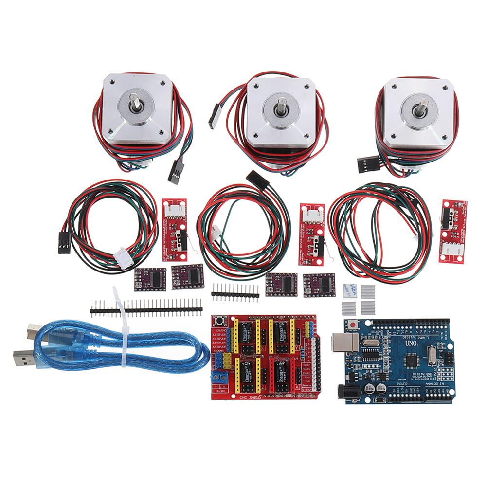
CNC Kit with UNO + Shield + Stepper Motor DRV8825 Endstop A4988 GRBL
$125.66DIY Electronic KitsAdd to cartThe kit contains following items 1x UNO R3+CH340G Board. It’s not official board but it’s compatible with all software and hardware. Licensed under Creative Commons Attribution Share-Alike license. 1X 40inch Gold plated/shielded USB cable w/noise suppressor. Essential for stable connection and printing. 1x CNC shield 3X Zyltech 1.5A 0.42 N.m stepper motors 3X Mechanical endstop …
CNC Kit with UNO + Shield + Stepper Motor DRV8825 Endstop A4988 GRBLRead More
with Housing DIY Music Spectrum LED Flash Kit + DIY Amplifier Speaker Kit
$63.73DIY Electronic KitsAdd to cartWith Housing DIY Music Spectrum LED Flash Kit + DIY Amplifier Speaker KitLED Flash Kit FeatureOperating voltage:5V USB power supplySignal access mode:3.5 audio line input audio signalInstallation:DIY welding assemblyDimensions:108 x 70 x 16mm (Length x high x thickness)Weight:130g (including housing)Type:With housing DIY kitPCB color:WhiteDIY Mini Speaker Kit FeatureInstallation:Circuit board assembly weldingSpeaker power:3W per channelCase Size:65 …
with Housing DIY Music Spectrum LED Flash Kit + DIY Amplifier Speaker KitRead More


Customers Also Viewed
50Pcs KW12-3 Micro Limit Switch with Roller Lever Open/Close Switch 5A 125V
$16.52Electronic Accessories & SuppliesAdd to cartFeaturesOperating temperature:-40°C to 70°CRated voltage:AC 125V-250VPer weight:2gCurrent rating:5ASize:20 x 10 x 6mm (L X W X H)PCB Terminals Circuit BoardWith Roller Lever LimitWorking principleBy external mechanical force transmission elements (by pins, buttons, levers, rollers, etc.) will be used to force action on a reed, producing reed instantaneous action when action shifted to the critical point, …
50Pcs KW12-3 Micro Limit Switch with Roller Lever Open/Close Switch 5A 125VRead More
129Pcs/Set Silicone Casting Molds and Tools Jewelry Pendant Resin Mould DIY
$20.24Lab TubesAdd to cartFeatures-This set of making tool is especially designed for DIY expoxy resin crafts, including silicone mold,spoon,sequin,drill,nails and so on.-Different silicone molds have different shapes for you to choose,which may accurately match your various needs.-It is easy control with the reliable quanlity as well as the efficence. -The superior DIY tools for your craft works.SpecificationMaterials:Silicone,MetalType:Making ToolsQuantity:129pcs,one …
129Pcs/Set Silicone Casting Molds and Tools Jewelry Pendant Resin Mould DIYRead More
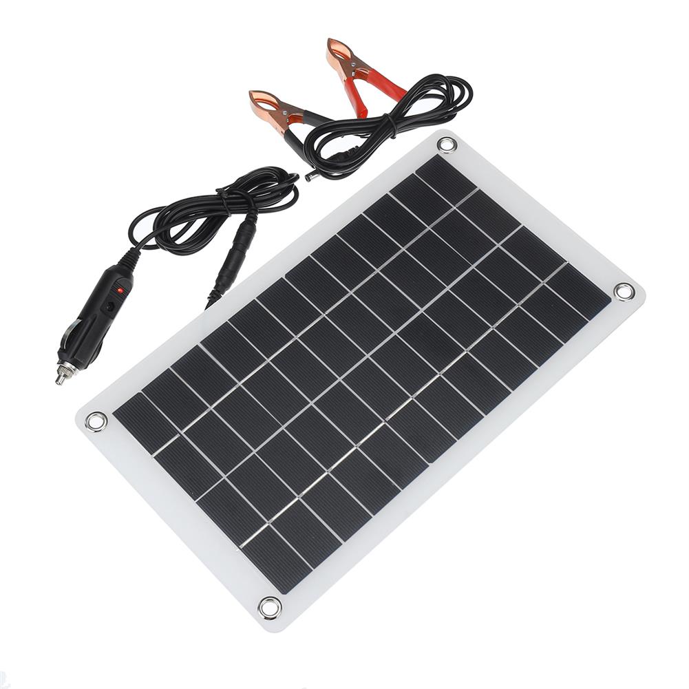
12V 7.5W Polysilicon Solar Panel Battery Charger Clip for Car RV Boat Outdoor
$60.74Solar PanelAdd to cartFeatures Lightweight and convenient to carry Long span life Easy to use Suitable for 12V battery, working temperature 0-60 ℃, reflow protectionSpecificationsMaterial:Grade A monocrystalline silicon solar panelPower:7.5W maxWorking voltage:12V (rechargeable 12V battery)Current:0-625MATemperature:-60 ° CSolar panel size:310 * 190mmPacking size:330 * 205 * 30mmNotice Make sure your battery is good and bad The level of the …
12V 7.5W Polysilicon Solar Panel Battery Charger Clip for Car RV Boat OutdoorRead More
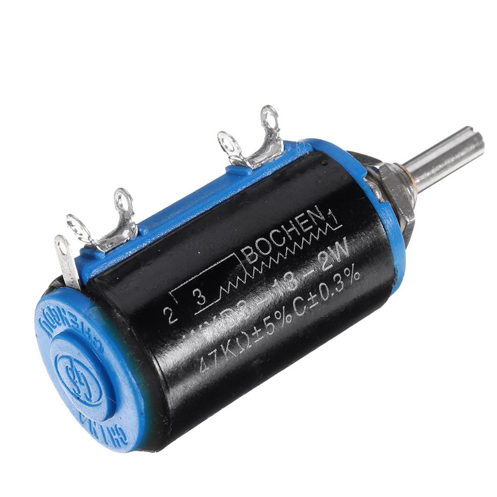
WXD3-13-2W Precision Potentiometer 470R 47K Ohm Wirewound Multi-Turn Potentiometer
$4.50Module ComponentsAdd to cartSpecificationsResistance range:47K┯Resistance tolerance:÷ 5%Rotation angle:3600 ÷ 20 Number of laps:10 lapsRated voltage:160VStarting torque:3.5 ~ 100mN.mRated power:2W (85 →) 0W (125 →)Linearity accuracy:÷ 0.3%Mechanical durability:10,000 weeksPackage included1 x Potentiometer
Mini Diving Equipment Scuba Diving Cylinder Scuba Oxygen Reserve Air Tank Set
$568.00Magnetic StirrerAdd to cartSpecificationsName:0.5L Portable Mini Oxygen Cylinder Air Oxygen Tank Breath DivingBreathing Oxygen CylinderCapacity:0.5LMaterial:Aviation aluminumOxygen cylinder weight:1040gOxygen cylinder dimension:φ6*35.5cm (2.4*14inch)Packing case size:65*10*38cm (25.6*4*15inch)Air capacity:3.0 Cu.Ft / 85 LittersMax. pressure:3000PSI / 200bar / 20MPaMax. dwell time underwater:10minNumber of underwater max. breathing:21 times(depending on individual lung capacity and depth of diving)High-pressure Inflatable PumpHigh pressure air pump material:stainless steelSize:62*26*3.6 cm(24.4*10*1.4inch)Barometer …
Mini Diving Equipment Scuba Diving Cylinder Scuba Oxygen Reserve Air Tank SetRead More
intelligent Dual LCD Pure Sine Wave Power inverter DC48V to AC220V 6000W for Home/Car/industry
$1,188.66InvertersAdd to cartSpecificationsType:Solar inverterOutput voltage waveform:Pure sine waveMatarial:Aluminum shellPower:6000WPeak Power:12000W (5000W Continous)Output voltage:220VInput voltage:48VInput DC low voltage protection:10V±0.5V DCInput DC high voltage protection:15.5V±0.5V DCOutput frequency:50Hz/60HzConversion rate:93% or moreSize:450x180x140mmWeight:8.9KG(Approx.)Appication:Home emergency/Industry/CarFeatures-High-precision circuit board.-Built-in intelligent control chip.-Dual LCD screen integration.-If the machine is abnormal, there will be an alarm.-Screw terminal. Pluggable plug, easy to replace the cable.-Universal socket, strong compatibility,most …
43.8V 1.6A Electric Bike Battery Charger for Scooter Power Supply Lithium Battery Charger
$46.56AC/DC AdaptersAdd to cartSpecificationsName:36V Lithium Battery Charger 43.8V 1.6AColor:BlackSize:155*90*50mm (6.1*3.5*2inch)Input:AC 100-240V 50-60HzOutput:DC 42V 0-2AInput plug:EU PlugOutput plug:1+, 3-Feature– This charger is suitable for all 36V lithium batteries.– Quick charge function.– Suitable for electric bicycle scooter.Package included1 x Lithium Battery Charger


Reviews
There are no reviews yet.