


5pcs Electronic DIY LED Dimming Lights Series and Parallel Circuit Technology Small Production Kit
$16.60
Shipping:Standard Shipping about 10-25 business days
Secure Payment:Paypal,VISA,MasterCard
Description
The purpose of the experiment
1. Understand and recognize the light-emitting diodes and illuminate the light-emitting diodes (LEDs);
2. Understand the role of understanding resistance, series and parallel resistance;
3. Understand the self-locking switch;
4. Understand and recognize adjustable resistors and use adjustable resistors;
Experimental steps
Step 1:The long leg of the light-emitting diode (LED) is the positive pole, and the short leg is the negative pole. First, the long wire of the LED is connected to the black wire (negative electrode) of the battery case, and the short leg of the LED is connected to the red wire (positive electrode) of the battery case. At this time, the light emitting diode (LED) is not lit. Then send it over again, let the long leg of the LED connect to the red line of the battery box, and the short leg of the LED is connected to the black line of the battery box. At this time, the LED lights up, indicating that the LED is in one-way operation and the single-pass characteristic of the diode .
Step 2:In the circuit of the experimental step 1, a resistor of 220 ohms is inserted in series, and the brightness of the LED lamp is lowered, and the resistance hinders the current.
Step 3:Connect a 220 ohm resistor in parallel with the resistance in the circuit of the experimental board 2. The brightness of the LED is increased, indicating that the total resistance of the resistor in the circuit is reduced after the resistors are connected in parallel.
Step 4:Change the two resistors of the experimental step 3 from parallel to series. After the series connection, the brightness of the LED lamp is the lowest. After the series connection of the resistors, the total resistance of the resistor in the circuit increases.
Step 5:Replace the original resistor with a potentiometer. The potentiometer has 3 feet, and the resistance of pins 1 and 3 is fixed. The resistance of pins 1 and 2, 2 feet and 3 feet can be changed by adjusting the potentiometer knob. When experimenting, you can pick up 2 of them. The foot has to experiment many times, adjust the potentiometer knob to observe the change of LED brightness, so that you can fully understand the potentiometer.
Step 6:Know the self-locking. Press and wait for the light to be on, then press the light to turn off.
Package included
5 x DIY LED Dimming Lights Technology Small Production Kit
| Weight | 0.135 kg |
|---|
Related products
5Pcs inverter Boost High Voltage Generator 15KV High Frequency Transformer
$28.50DIY Electronic KitsAdd to cartUseSchool science experiment, electronic equipment, negative ion generator, small scientific production and so on. FeatureThis circuit works to produce a stable high-frequency arc, the temperature is extremely high, can easily ignite the combustible, so it was called a plasma lighter.NoteThis transformer high voltage winding in the inner layer, is the segment skeleton wound, low voltage …
5Pcs inverter Boost High Voltage Generator 15KV High Frequency TransformerRead More
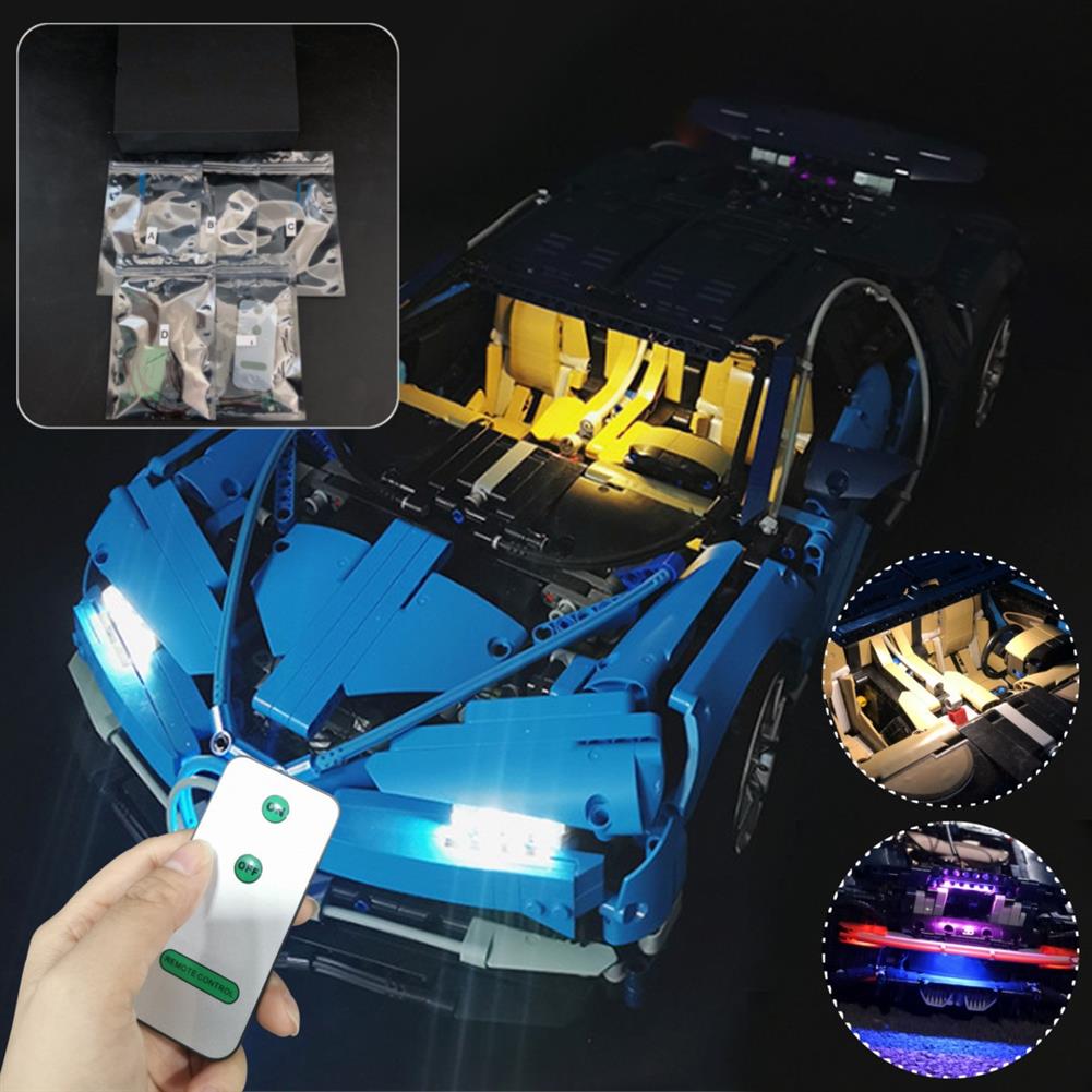
DIY LED Light Lighting Kit for LEGO 42083 Bugatti Chiron Technic Set with Remote
$37.17DIY Electronic KitsAdd to cartUpgrade LED Light Kit With Remote Control For Bugatti Chiron 42083 Technic Advanced Building Light SetFeature100% Brand new.Light Kit will turn your model into a true spectacle and really bring the supercar to life. With front and rear headlights, including our specially developed light bar that stretches across the rear of the vehicle, your model …
DIY LED Light Lighting Kit for LEGO 42083 Bugatti Chiron Technic Set with RemoteRead More
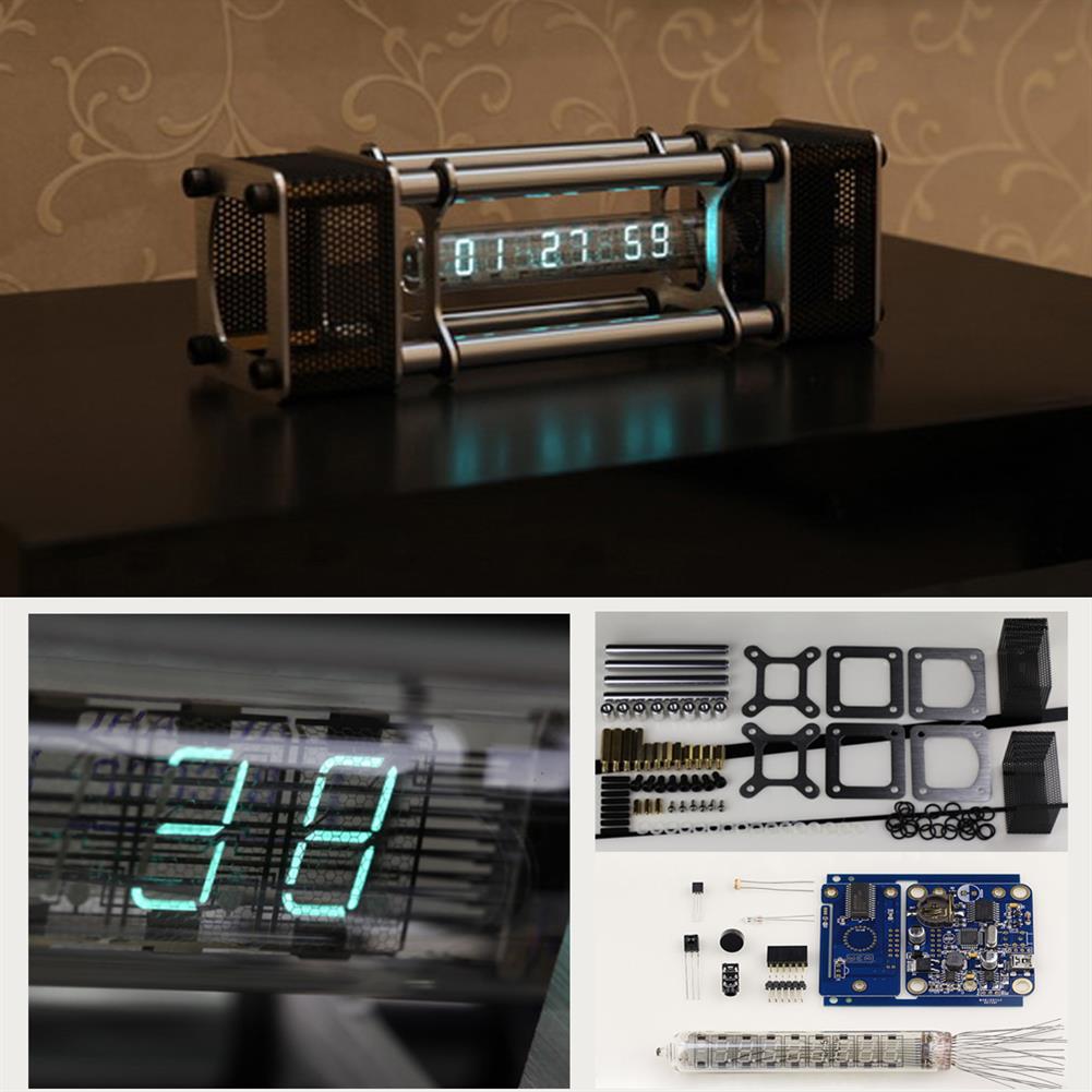
Unassembled IV-18 Fluorescent Tube Clock Kit DIY 6 Digital Display Energy Pillar with Remote Control
$328.40DIY Electronic KitsAdd to cartUser manual:http://img.staticbg.com/file/products/20180621033457IV-18-VFD-tube-Clock-Manual-EN-v1.2.0.pdfAssembly Instruction:http://www.nixieclock.org/p=449BOM list:http://img.staticbg.com/file/products/20180621211231IV-18-VFD-tube-Clock-kit-BOM-EN-v1.2.0.pdfFeatureInput voltage:DC 5VOperating current:220mA maximumFluorescent tube model:IV-18 (B-18 1984-1992 manufactured by the former Soviet Union)Dimensions:200mm x 52mm x 64mm (L x W x H) fluorescent tube length 115mm diameter 18mmWorking temp:0°C – 60°C Net Weight:350g Shell material:Aluminum alloy Functional features1. Eight digits in IV-18 (-18) VFD tube display. (~1980-1992 made in USSR). …


Customers Also Viewed
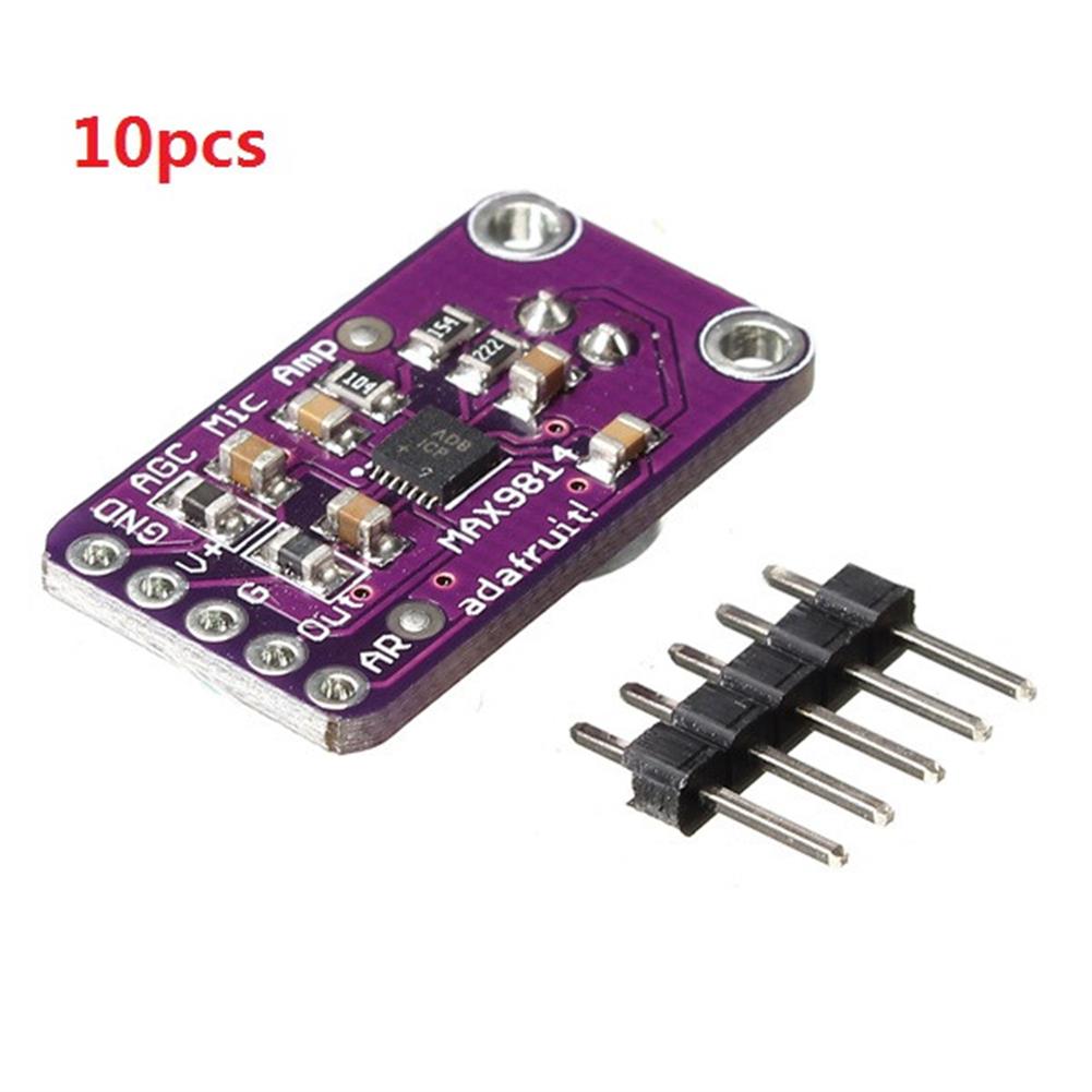
10pcs MAX9814 High Performance Microphone AGC Amplifier Module CMA-4544PF-W
$90.79Amplifier BoardAdd to cartSpecifications– Supply Voltage:2.7v-5.5v @ 3mA current– Output:2Vpp on 1.25V bias– Frequency Response:20Hz – 20KHz– Programmable Attack and Release Ratio– Automatic gain, selectable max from 40dB, 50dB or 60dB– Low Input-Referred Noise Density of 30nV/– Low THD:0.04% (typ)– Low Power Shutdown Mode– Built-in 2V low-noise microphone bias– -40°C ~ +85°C extended temperature rangePackage included10 x Microphone …
10pcs MAX9814 High Performance Microphone AGC Amplifier Module CMA-4544PF-WRead More
T-AMP 2 x 15W TA2024 Digital Audio Amplifier Board Mini AMP
$19.04Amplifier BoardAdd to cartFeature1. The power to more than 12V current 3A2. The speaker is best to use an impedance of 4 ohms, some of the high sensitivity3. For some signal level is relatively low tone, to add the preamplifier to play the effect4. Note the positive and negative can not be reversed, use the power supplyElectrical CharacteristicsIts …
T-AMP 2 x 15W TA2024 Digital Audio Amplifier Board Mini AMPRead More
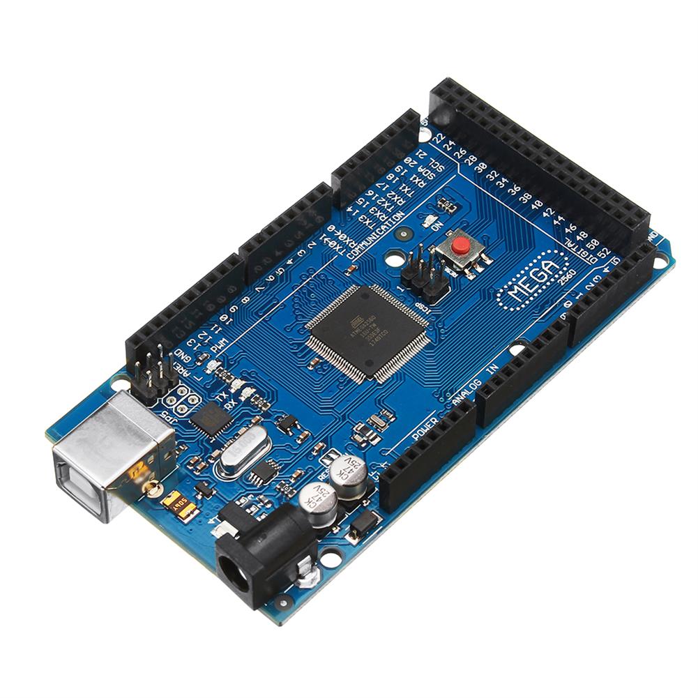
Mega 2560 R3 ATmega2560-16AU Control Module without USB Cable
$44.54Motherboard & Development BoardAdd to cartDescriptionThis is compatible R3 Mega2560 ATmega2560-16AU control board without USB cableMega is an ATmega2560 as core microcontroller development board itself has 54 groups digital I / O input / output terminal (14 groups do PWM outputs), 16 sets of simulation than the input side, group 4 UARTs (hardware serial ports), using the 16 MHz crystal …
Mega 2560 R3 ATmega2560-16AU Control Module without USB CableRead More
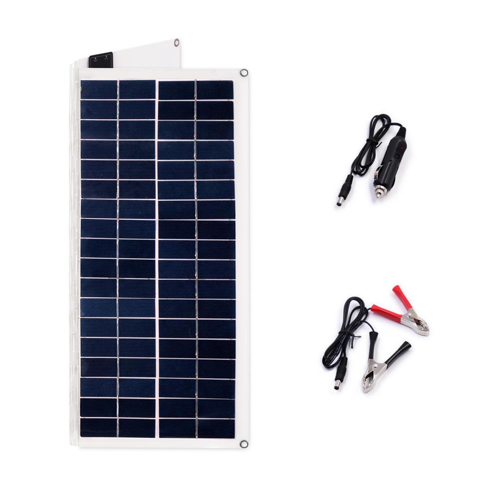
20W 420*380*3mm Folding PET Monocrystalline Silicon Solar Panel with Cable Dual USB
$93.62Smart Robot & Solar PanelAdd to cartSpecificationsMaximum Power(Pmax):20WOpen Circuit Voltage(Voc):18VMaximum Power Voltage(Vmp):12vMaximum Power Current(Imp):1.1AMaximum System Voltage(Imp):1000vOutput:USB 5V & DC 18VQuantity of cell:36Cell Effcience %:20%Output Tolerance:±10%Size:425*380*3mmStandard Test Conditions:Irradiance 1000w/m2Temoerature 25.C,AM=1.5Package Included1 x Solar panel with cable
5pcs 8Channel DC 5V RS485 Modbus RTU Control Module UART Relay Switch Board PLC
$45.10Relay ModuleAdd to cartDescriptions– Operating Voltage:DC 5V(5V Version)– Operating Current:10-15MA– inchopeninch inchcloseinch inchMomentaryinch inchSelf-lockinginch inchInterlockinch inchDelayinch 6 Commands– Two instruction-control mode:AT command and MODBUS command– Under the AT command ,the maximum delay is 9999 seconds– Under the MODBUS command ,the maximum delay is 255 seconds– AT commands can be made serial HyperTerminal (serial assistant) Enter;– MODBUS commands can …
5pcs 8Channel DC 5V RS485 Modbus RTU Control Module UART Relay Switch Board PLCRead More
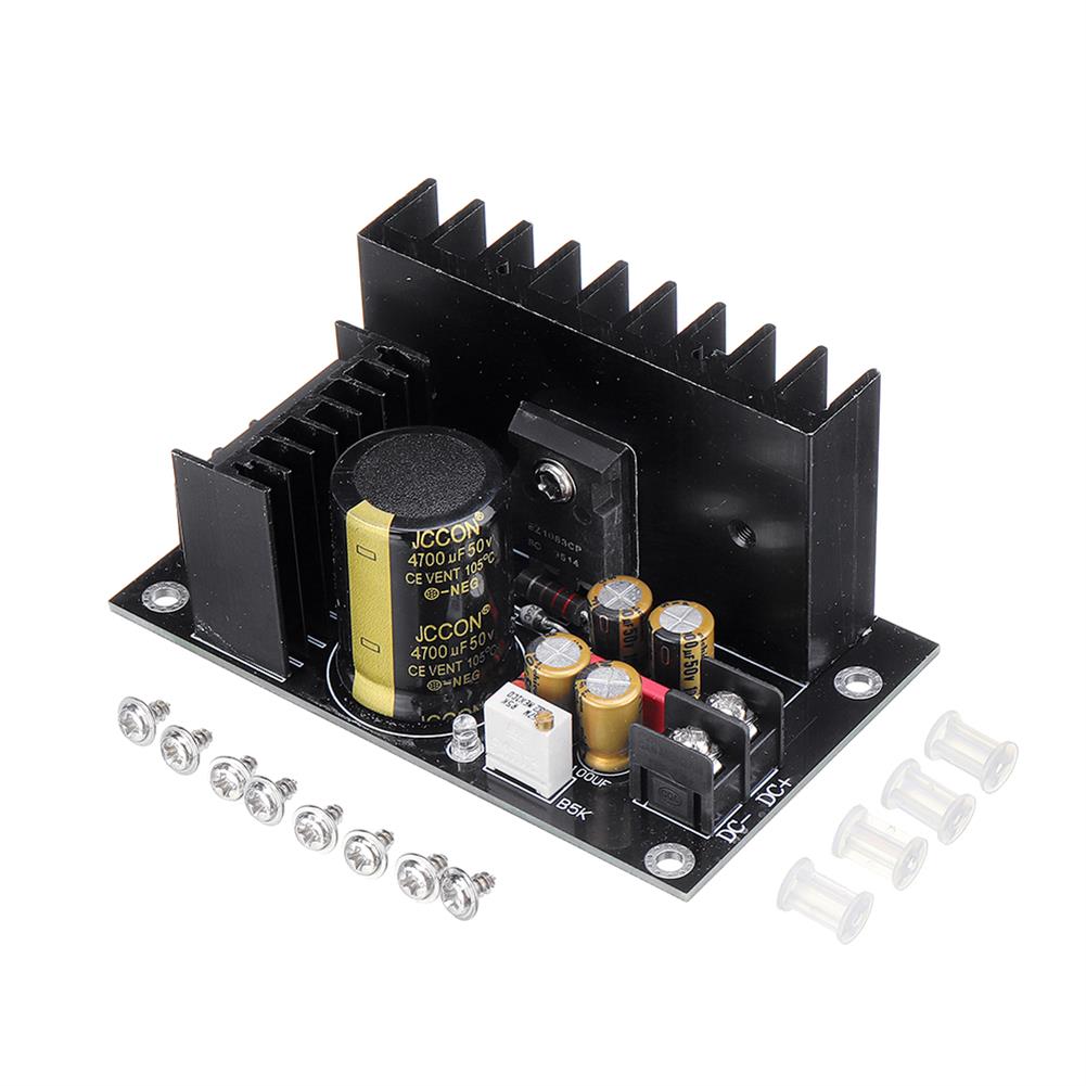
LT1083cp 7A AC 35V Rectifier Filter Power Supply Board DIY Home theater Sound Amplifier Voltage Regulator
$24.04Power Supply ModuleAdd to cartDescriptionLT1083CP feature description (emphasis):It is a linear step-down block. Although the voltage adjustment can be adjusted from 2.5V to 37V, it is recommended that the working differential pressure is within 10V, because the power consumption is proportional to the differential pressure, the greater the differential pressure, the more heat The larger the output current, the …


Reviews
There are no reviews yet.