


3pcs Electronic DIY LED Dimming Lights Series and Parallel Circuit Technology Small Production Kit
$10.56
Shipping:Standard Shipping about 10-25 business days
Secure Payment:Paypal,VISA,MasterCard
Description
The purpose of the experiment
1. Understand and recognize the light-emitting diodes and illuminate the light-emitting diodes (LEDs);
2. Understand the role of understanding resistance, series and parallel resistance;
3. Understand the self-locking switch;
4. Understand and recognize adjustable resistors and use adjustable resistors;
Experimental steps
Step 1:The long leg of the light-emitting diode (LED) is the positive pole, and the short leg is the negative pole. First, the long wire of the LED is connected to the black wire (negative electrode) of the battery case, and the short leg of the LED is connected to the red wire (positive electrode) of the battery case. At this time, the light emitting diode (LED) is not lit. Then send it over again, let the long leg of the LED connect to the red line of the battery box, and the short leg of the LED is connected to the black line of the battery box. At this time, the LED lights up, indicating that the LED is in one-way operation and the single-pass characteristic of the diode .
Step 2:In the circuit of the experimental step 1, a resistor of 220 ohms is inserted in series, and the brightness of the LED lamp is lowered, and the resistance hinders the current.
Step 3:Connect a 220 ohm resistor in parallel with the resistance in the circuit of the experimental board 2. The brightness of the LED is increased, indicating that the total resistance of the resistor in the circuit is reduced after the resistors are connected in parallel.
Step 4:Change the two resistors of the experimental step 3 from parallel to series. After the series connection, the brightness of the LED lamp is the lowest. After the series connection of the resistors, the total resistance of the resistor in the circuit increases.
Step 5:Replace the original resistor with a potentiometer. The potentiometer has 3 feet, and the resistance of pins 1 and 3 is fixed. The resistance of pins 1 and 2, 2 feet and 3 feet can be changed by adjusting the potentiometer knob. When experimenting, you can pick up 2 of them. The foot has to experiment many times, adjust the potentiometer knob to observe the change of LED brightness, so that you can fully understand the potentiometer.
Step 6:Know the self-locking. Press and wait for the light to be on, then press the light to turn off.
Package included
3 x DIY LED Dimming Lights Technology Small Production Kit
| Weight | 0.081 kg |
|---|
Related products
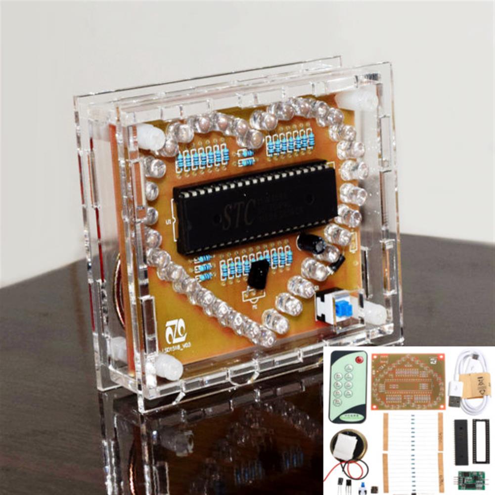
DC 5V DIY Colorful MP3 Music Heart-shaped RGB LED Flash Kit
$28.62DIY Electronic KitsAdd to cartVideo Feature Size:92 x 79.5 x 29mm model:STC15W408S Operating voltage:DC 5V (Or USB) Remote control:9-key infrared remote control (need to be aligned with the infrared receiver, no need pairing) Music:You can replace the music, you can also insert the U disk playback (only supports MP3 format) Sound output:8ohm 1W Measured speaker distance:65dB (1M) Speaker size:4cm …
DC 5V DIY Colorful MP3 Music Heart-shaped RGB LED Flash KitRead More
Transparent Module Case Housing Shell for Upgrade DIY EC1515B DS1302 LED Electronic Clock Kit
$13.11DIY Electronic KitsAdd to cartTransparent Case Housing Shell For Upgrade DIY EC1515B DS1302 LED Electronic Clock Kit Feature This is for ID 1053190 only, used as spare parts and maintenance. The DIY clock kit is not included. Color:Transparent Note The color of the new case is blue as follwing picture, which is not affect the function. Package included 1 …
3Pcs DIY CD4060 SMD Music LED Light Kit Electronic Experimental Training Teaching
$20.61DIY Electronic KitsAdd to cartWorking principleUsing the SMD CD4060 control 12 red, yellow and green LED flashing, adjust RP1 can change the speed of flashing, while the music chip issued a wonderful music. The kit uses SMD components and plug-in components, is ideal for practical training requirements.The CD4060 consists of an oscillator and a 14-bit binary serial counter bit. …
3Pcs DIY CD4060 SMD Music LED Light Kit Electronic Experimental Training TeachingRead More


Customers Also Viewed
28.35ct 20x15mm Purple Oval Elliptical Cut Gemstone VVS AAA Jewelry Loose Gems Decorations
$20.24Lab Clamp & StandAdd to cartSpecificationsMaterial:ZirconColor:PurpleSize:20x15mmWeight:28.35ctClarity:VVS AAAShape:OvalFeatures– Transparent, bright;– Color is bright and the purity is positive;– Wide range of use;– Application for jewelry.Package Included1 Pcs x Purple Oval Cut Gemstone
5pcs CJMCU-250E BMA250E Sensor Module 3-axis Low G Acceleration Sensor Triaxial Accelerometer SPI IIC interface
$32.02Sensor & Detector ModuleAdd to cartFeatureThe BMA250E is a triaxial, low-g acceleration sensor with digital output for consumer applications. It allows measurements of acceleration in three perpendicular axes. An evaluation circuitry (ASIC) converts the output of a micromechanical acceleration-sensing structure(MEMS) that works according to the differential capacitance principle.Package and interfaces of the BMA250E have been defined to match a multitude …
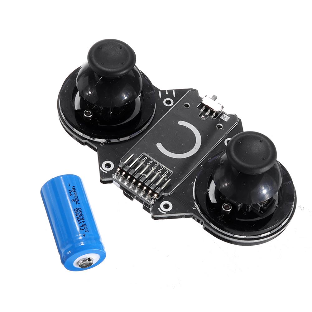
JoyC Rocker Sensor Switch Module STM32F030F4 Control Chip Game Handle I2C Wireless Joystick Device
$54.05Motherboard & Development BoardAdd to cartDescriptionJoyC is a rocker module designed for the M5StickC.It supports two-hand operation. Embedded STM32F030F4 main control chip, using I2C communication protocol and host M5StickC for data transmission. The ran ge of the joystick is 0~200, there are 12 RGB LEDs under the left and right joysticks, and the bottom of the joystick is equipped with …
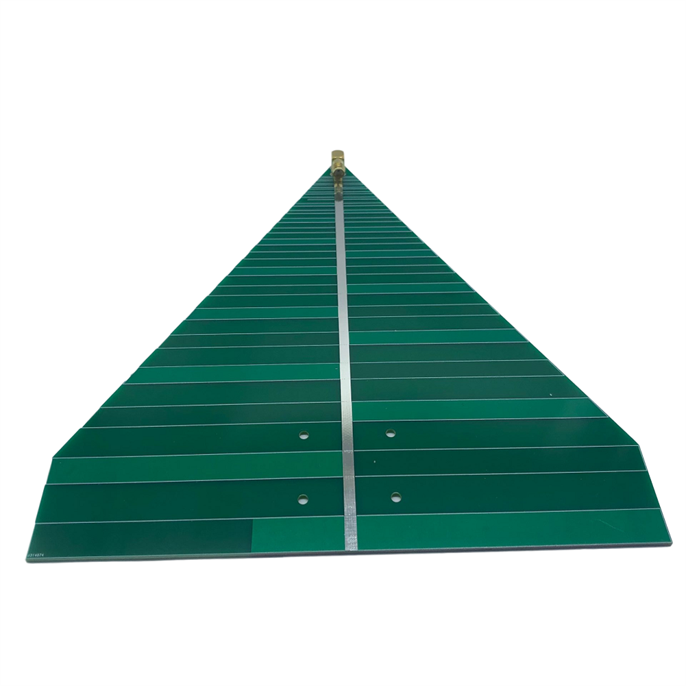
600-6000MHz UWB WiFi Ultra-wideband Log Periodic Antenna
$32.00RF amplifierAdd to cartSpecification1. Antenna frequency:600-6000MHz2. Antenna standing wave:less than 2 (typical value)3. Antenna polarization:directional linear polarization4. Antenna gain:6-7dB5. Power capacity:50W6. Dimensions:20≠20CM7. Weight:74 g8. Connector form:SMA-K (standard female, outer screw and inner hole)Package included1 x Antenna


Recently Viewed Products
-
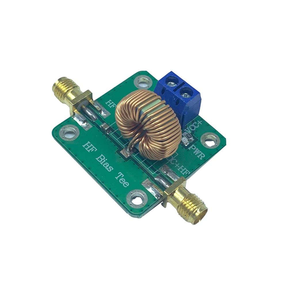 RF Microwave DC Bias DC Block DC Feed DC Bias 0.2-180MHz Module $21.86
 -
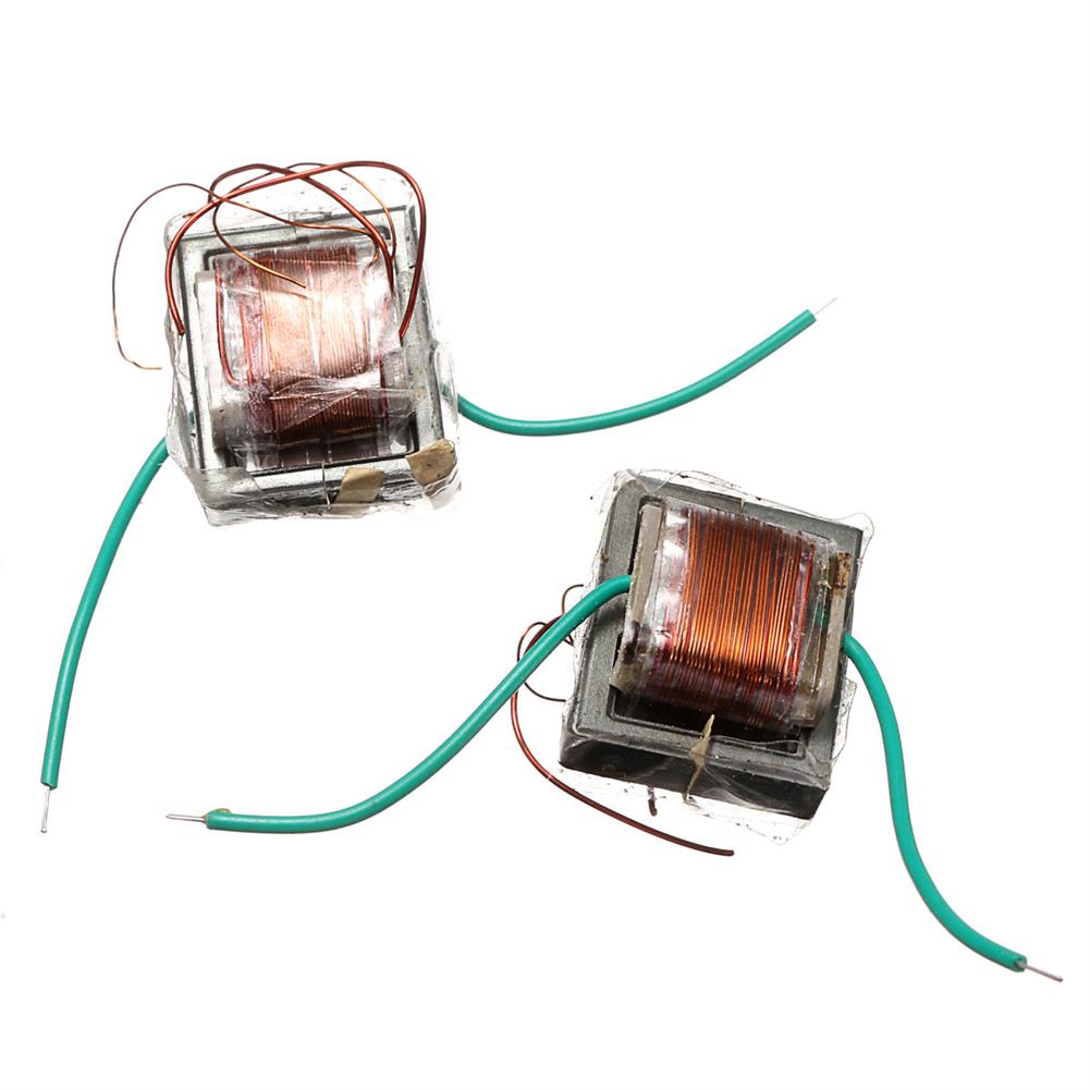 10Pcs 10KV High Frequency High Voltage Transformer Booster Coil inverter $20.07
 -
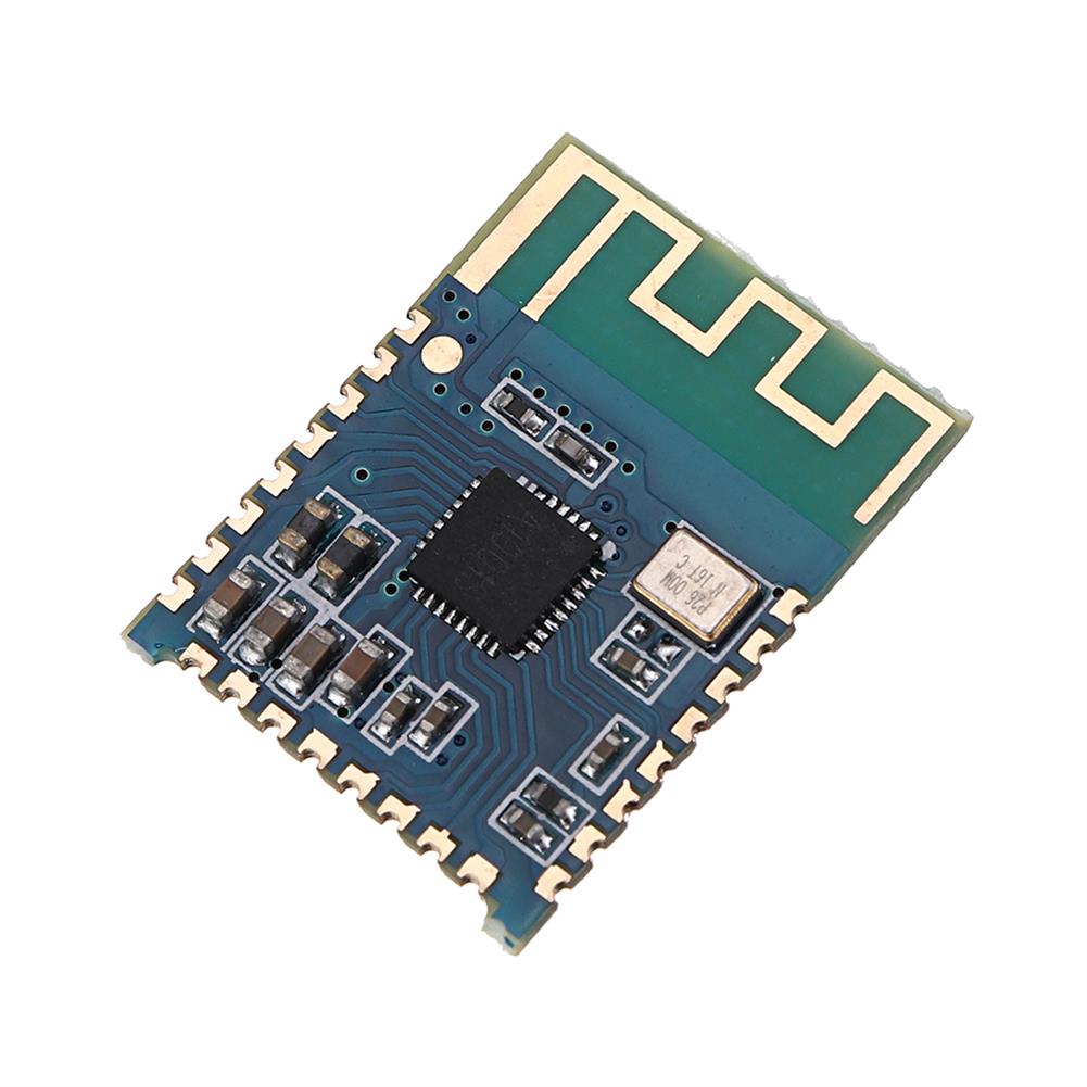 3pcs DC3.3-4.2V JDY-64 Lossless Bluetooth 4.2 Module Stereo Audio bluetooth Board $14.89
 -
 24/40 Glass Oil Water Receiver Separator Essential Oil Distillation Kit Part Lab $83.01
 -
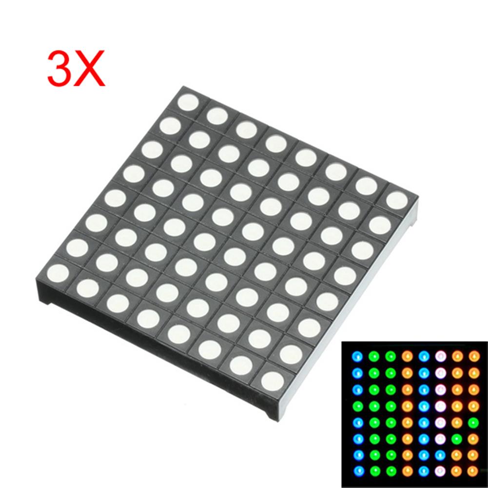 3Pcs 3-color Common Anode RGB LED Dot Matrix Display Module Compatible Colorduino $30.64
 -
 3.3V To 5V/12V/24V 4 Channel Optocoupler Isolation Board Isolated Module PNP Output PLC Signal Level Voltage Converter $15.30
 -
 220V 45W 2 Type Portable Bladeless Tower Air Standing Fan 3 Speed Remote Control Purifier $194.35
 -
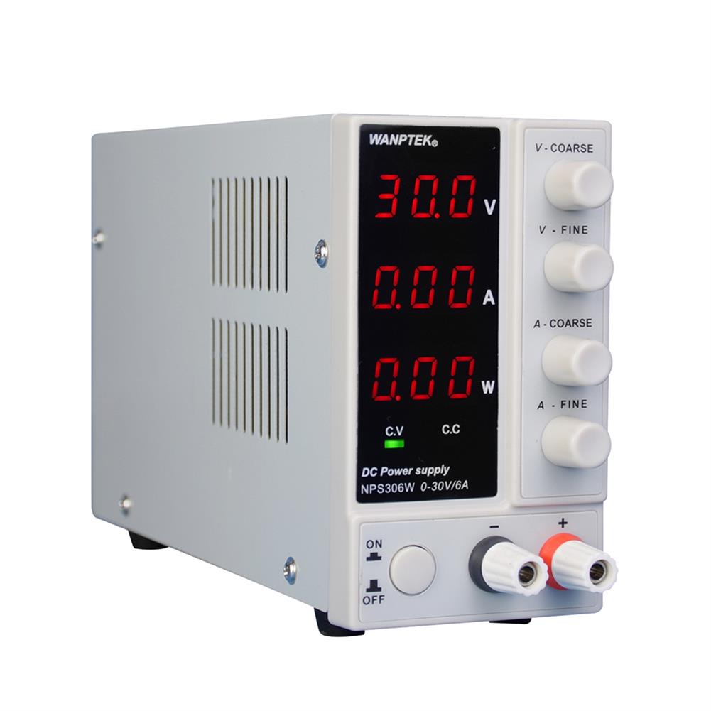 Wanptek NPS306W 110V/220V 0-30V 0-6A Adjustable Digital DC Power Supply 180W Regulated Laboratory Switching Power Supply $170.09
 -
 YAHBOOM official Raspberry Pi Camera Module V2 Compatible with Raspberry Pi and Jetson NANO $84.96
 -
 10W Magic Array Qi Wireless Fast Charging Pad for IPhone X XS XR/Samsung/HuaWei Charging Board $123.51
Reviews
There are no reviews yet.