


Dual Modbus-Rtu 2-way Relay Module Switch input and Output RS485/TTL Communication Controller
$19.35
Shipping:Standard Shipping about 10-25 business days
Secure Payment:Paypal,VISA,MasterCard
Description
LC 2 channel Modbus relay module equipped with mature and stable 8-bit MCU and RS485 level communication chip, adopt standard MODBUS RTU format RS485 communication protocol. It can realize 2bit input signal detection and 2-bit relay output. It can be used for digital detection or power control occasions.
Features
1. Support Modbus RTU protocol
2. Support RS485/TTL UART interface
3. Output indicator in multi-mode
4. The address can be set
5. Support input reverse connection protection
6. Relay switch output
7. Support parameter memory function
Parameters
1. Item name:Dual Modbus Relay Module
2. Work voltage:DC 7V~24V
3. Baud rate:4800/9600/19600bps(default 9600bps)
4. Optocoupler input signal:DC 3.3V~30V
5. Set address:1~255
6. Relay control mode:ON/OFF, Delay_ON, Delay_OFF mode
7. Delay time:0~6553.5s
8. Load:AC 250V 10A or DC 28V 10A
9. Protocol:Modbus RTU
10. Interface:RS485/TTL UART
11. Control channel:2channel
12. Operating Temperature:-20→~85→
13. Operating Humidity:5%~95%RH
14. Module Size:85 x 49 x 19mm
Modbus RTU Command
1. Suppose the device address is 0xFF so return 00 10 00 00 00 01 02 00 FF EB 80 and the 9th byte is device address.
2. Turn ON CH_1 Relay (Normal Mode)
Send:FF 05 00 00 FF 00 99 E4
Return:FF 05 00 00 FF 00 99 E4
Note_1:The 3rd and 4th byte are relay addresses. So it can be 0x0000, 0x0001, 0x0002, 0x0003.
Note_2:The 5th and 6th byte are relay data. 0xFF00 means turn ON relay and 0x0000 means turn OFF relay.
3. Turn OFF CH_1 Relay(Normal Mode)
Send:FF 05 00 00 00 00 D8 14
Return:FF 05 00 00 00 00 D8 14
4. Turn ON CH_2 Relay(Normal Mode)
Send:FF 05 00 01 FF 00 C8 24
Return:FF 05 00 01 FF 00 C8 24
5. Turn OFF CH_2 Relay(Normal Mode)
Send:FF 05 00 01 00 00 89 D4
Return:FF 05 00 01 00 00 89 D4
6. Turn ON All relays
Send:FF 0F 00 00 00 08 01 FF 30 1D
Return:FF 0F 00 00 00 08 41 D3
7. Turn OFF All relays
Send:FF 0F 00 00 00 08 01 00 70 5D
Return:FF 0F 00 00 00 08 41 D3
8. Set device address to 0x01
Send:00 10 00 00 00 01 02 00 01 6A 00
Return:00 10 00 00 00 01 02 00 01 6A 00
Note:The 9th btye is device address.
9. Set device address to 0xFF
Send:00 10 00 00 00 01 02 00 FF EB 80
Return:00 10 00 00 00 01 02 00 FF EB 80
10. Read device address
Send:00 03 00 00 00 01 85 DB
Return:00 03 02 00 FF C5 C4
Note:The 5th btye is device address.
11. Read relay status
Send:FF 01 00 00 00 08 28 12
Return:FF 01 01 01 A1 A0
Note:The 4th means which one relay. 0 means OFF and 1 means ON.
12. Read optocoupler input staturs
Send:FF 02 00 00 00 08 6C 12
Return:FF 02 01 01 51 A0
Note:The 4th means which one input. 0 means low level signal input and 1 means high level signal input.
13. Set baud rate 4800bps
Send:FF 10 03 E9 00 01 02 00 02 4A 0C
Return:FF 10 03 E9 00 01 C5 A7
Note:The 9th btye is baud rate value. 0x02 is 4800bps. 0x03 is 9600bps. 0x04 is 19200bps.
14. Set baud rate 9600bps
Send:FF 10 03 E9 00 01 02 00 03 8B CC
Return:FF 10 03 E9 00 01 C5 A7
15. Set baud rate 19200bps
Send:FF 10 03 E9 00 01 02 00 04 CA 0E
Return:FF 10 03 E9 00 01 C5 A7
16. Turn ON CH_1 Relay(2S Flashing Mode)
Send:FF 10 00 03 00 02 04 00 04 00 14 C5 9F
Return:FF 10 00 03 00 02 A4 16
Note_1:The 3rd and 4th byte are relay addresses. So CH1~CH4 can be 0x0003, 0x0008, 0x000D, 0x0012.
Note_2:The 10th and 11th byte are delay time in second. The minimum delay time is 0.1s. The relay will OFF after delay time. So the delay time in this command is:0x0014*0.1=2S.
17. Turn OFF CH_1 Relay(3S Flashing Mode)
Send:FF 10 00 03 00 02 04 00 02 00 1E A5 99
Return:FF 10 00 03 00 02 A4 16
Note:Relay will ON after delay time. So the delay time in this command is:0x001E*0.1=3S.
Package includes
1 x Dual Modbus Relay Module
| Weight | 0.045 kg |
|---|
Related products
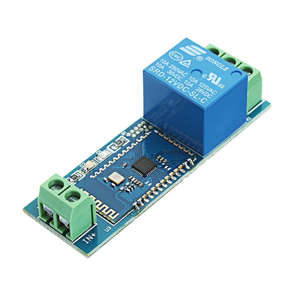
DC 12V bluetooth Relay Board Mobile Phone bluetooth Remote Control Switch
$19.67Relay ModuleAdd to cartSummarizeDC 12V bluetooth relay board include single channel 12V/10A relay module and SPP-C bluetooth serial port slave module, Can be sent via mobile phone APP commands to control the relay switch.Tools and manual download:Click here to openFunctional features(1) Onboard SPP – C bluetooth serial port slave module, with wireless control function.(2) Onboard 12 v,10 A …
DC 12V bluetooth Relay Board Mobile Phone bluetooth Remote Control SwitchRead More
5pcs QF1023-A-10S Timing Relay Delay Switch Relay Delay Timer Switch Timing Relay 10S Adjustable
$25.79Relay ModuleAdd to cartSpecificationsWorking voltage:12V DCDelay length:0-10SAccuracy:1/100Error:2%Delay:using single chip delayPCB size:70*26*18mmInstallation hole center distance:64mmAperture:3mmFunction:Turn on the relay immediately after power-on, and automatically break after a period of time;Special reminder:This is not a power-off delay disconnect module, the relay will be disconnected immediately when the input power is disconnected.Package Included5 x QF1023-A-10S Timing Relay Delay Switch Relay Delay Timer …
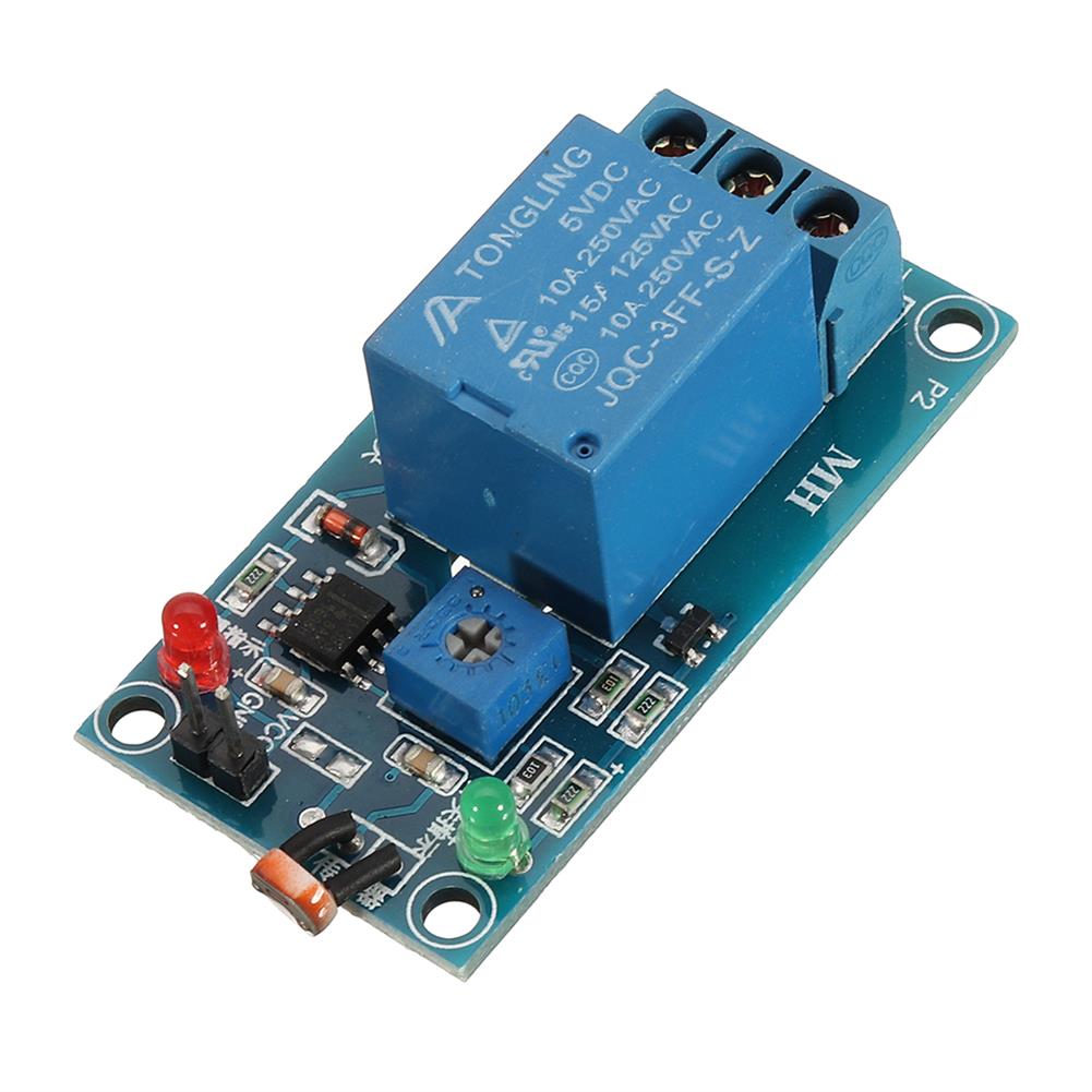
Photosensitive Resistance Sensor with Relay Module 5V Optical Control Switch Light Detection Switch
$7.11Relay ModuleAdd to cartUsageLight detection, brightness detection, potentiometer can be adjusted to detect the brightness of the valve point, with its own relay, can do a variety of brightness detection switch.Features1. Using the photoresistor to induce the intensity of light, with its own relay, directly control the load2. Adjust the sensitivity with the potentiometer. Set the start relay …


Customers Also Viewed
5pcs 3S NiMH NiCd Rechargeable Battery Charger Charging Module Board input DC 5V
$26.35Power Supply ModuleAdd to cartDescriptions3-Cell(3S) VersionInput voltage:DC 4.5V-5.5V(Recommend DC 5V)Charging voltage about:4.05V-5.1VCharging current about:230mA-240mAUSB power protectionShort circuit protection and zero volt battery activationBattery protectionOperating ambient temperature:-40° to +85°Storage temperature:-65° to +125°Size:30x 15 x 4mmNoteThe output voltage cannot be measured with a multimeter without a battery. But can be observed with an oscilloscope.Applicationskids toys carDigital CamerasSolar chargingBluetooth ApplicationsAudio equipmentDigital CameraElectronic …
5pcs 3S NiMH NiCd Rechargeable Battery Charger Charging Module Board input DC 5VRead More
5Pcs/Pack 5V 1000mA 165*165mm Monocrystalline Solar Panel Cells with Positive&Negative Cables
$85.54Smart Robot & Solar PanelAdd to cartFeaturesProvide you with high conversion rate and incredibly efficient output.Excellent performance even under the weak sunlight.Portable and solid casing.Application:to charge, for home lighting and different kinds of low-power appliances, for science projects, for solar powered water pump, small solar power system, etc.SpecificationsType:Monocrystalline Size:165*165mmCurrent:1000mA Net Weight:about 600g one packPackage Content:5Pcs x Poly Solar PanelVoltage:5VMPN:Does Not ApplyPackage …
Waveshare 1.54 inch ink Screen Module 152×152 Electronic Paper SPI interface Yellow Black and White 3-color Display
$45.91Display ScreenAdd to cartDocumentsSchematic:Click here to openSample tutorial:Click here to openDatasheet:Click here to openGithub:Click here to openFeaturesNo backlight is needed, and the display content of the last screen can be kept for a long time after power offVery low power consumption, basically only consumes power when refreshingSPI control interface, can be connected to Raspberry/Nucleo and other main control …
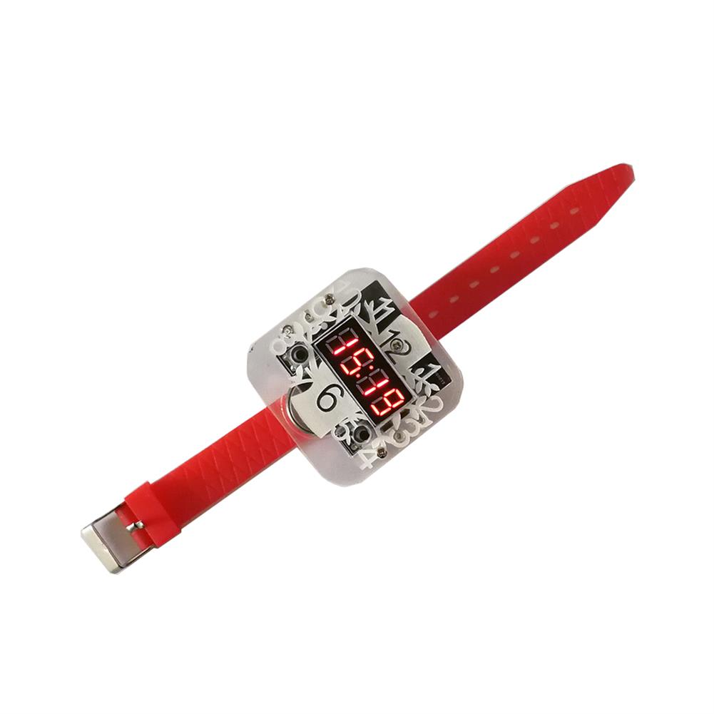
Geekcreit DIY Creative Electronic Watch Kit 51 Single-chip LED Digital Tube Clock Training Production Kit
$15.30DIY Electronic KitsAdd to cartDescriptionName:LED Electronic Watch KitPower supply:CR2025 3V button battery (available for testing, there are inevitably extra factors causing insufficient power.)Display:LED red digital tube displaySize:52*52*18mmInstallation:the board need to solder yourself and then assembly the caseFunction:You can press the digital tube button when need to wacth time; it will enter the power saving mode automatically after 5 seconds. …
QFN32 QFP32 Converter SMD To DIP Adapter PCB Universal Board
$3.56Expansion Board & ShieldAdd to cartQFN32 QFP32 Converter SMD To DIP Adapter PCB Universal BoardSpecificationDimension:20.25 x 40.64mm / 0.79inch x 1.60inchThickness:1.5mmPanel:FR4DescriptionThe PCB board has two sides.A side for pin pitch size 0.80mm, B side for pin pitch size 0.80mm.It can be used to convert QFN32/QFP32 (600mil width, 2.54mm pin pitch).You can solder filter capacitors or resistors to increase stability and …
QFN32 QFP32 Converter SMD To DIP Adapter PCB Universal BoardRead More
YJ0007 180W Car Stereo Audio Amplifier Power Boost Board Single 12V input Conversion Double 32V Output
$52.41Boost & Buck ModuleAdd to cartDescriptionAll parts and components of this product are original products, unpretentious and pure in quality; using high-quality original parts not only guarantees safety and quality, but also has a long service life, and more importantly, it is a strong guarantee that the actual performance can reach the design goals.Features1. All components are genuine.2. The main …


Reviews
There are no reviews yet.