


Dual Modbus-Rtu 2-way Relay Module Switch input and Output RS485/TTL Communication Controller
$19.35
Shipping:Standard Shipping about 10-25 business days
Secure Payment:Paypal,VISA,MasterCard
Description
LC 2 channel Modbus relay module equipped with mature and stable 8-bit MCU and RS485 level communication chip, adopt standard MODBUS RTU format RS485 communication protocol. It can realize 2bit input signal detection and 2-bit relay output. It can be used for digital detection or power control occasions.
Features
1. Support Modbus RTU protocol
2. Support RS485/TTL UART interface
3. Output indicator in multi-mode
4. The address can be set
5. Support input reverse connection protection
6. Relay switch output
7. Support parameter memory function
Parameters
1. Item name:Dual Modbus Relay Module
2. Work voltage:DC 7V~24V
3. Baud rate:4800/9600/19600bps(default 9600bps)
4. Optocoupler input signal:DC 3.3V~30V
5. Set address:1~255
6. Relay control mode:ON/OFF, Delay_ON, Delay_OFF mode
7. Delay time:0~6553.5s
8. Load:AC 250V 10A or DC 28V 10A
9. Protocol:Modbus RTU
10. Interface:RS485/TTL UART
11. Control channel:2channel
12. Operating Temperature:-20→~85→
13. Operating Humidity:5%~95%RH
14. Module Size:85 x 49 x 19mm
Modbus RTU Command
1. Suppose the device address is 0xFF so return 00 10 00 00 00 01 02 00 FF EB 80 and the 9th byte is device address.
2. Turn ON CH_1 Relay (Normal Mode)
Send:FF 05 00 00 FF 00 99 E4
Return:FF 05 00 00 FF 00 99 E4
Note_1:The 3rd and 4th byte are relay addresses. So it can be 0x0000, 0x0001, 0x0002, 0x0003.
Note_2:The 5th and 6th byte are relay data. 0xFF00 means turn ON relay and 0x0000 means turn OFF relay.
3. Turn OFF CH_1 Relay(Normal Mode)
Send:FF 05 00 00 00 00 D8 14
Return:FF 05 00 00 00 00 D8 14
4. Turn ON CH_2 Relay(Normal Mode)
Send:FF 05 00 01 FF 00 C8 24
Return:FF 05 00 01 FF 00 C8 24
5. Turn OFF CH_2 Relay(Normal Mode)
Send:FF 05 00 01 00 00 89 D4
Return:FF 05 00 01 00 00 89 D4
6. Turn ON All relays
Send:FF 0F 00 00 00 08 01 FF 30 1D
Return:FF 0F 00 00 00 08 41 D3
7. Turn OFF All relays
Send:FF 0F 00 00 00 08 01 00 70 5D
Return:FF 0F 00 00 00 08 41 D3
8. Set device address to 0x01
Send:00 10 00 00 00 01 02 00 01 6A 00
Return:00 10 00 00 00 01 02 00 01 6A 00
Note:The 9th btye is device address.
9. Set device address to 0xFF
Send:00 10 00 00 00 01 02 00 FF EB 80
Return:00 10 00 00 00 01 02 00 FF EB 80
10. Read device address
Send:00 03 00 00 00 01 85 DB
Return:00 03 02 00 FF C5 C4
Note:The 5th btye is device address.
11. Read relay status
Send:FF 01 00 00 00 08 28 12
Return:FF 01 01 01 A1 A0
Note:The 4th means which one relay. 0 means OFF and 1 means ON.
12. Read optocoupler input staturs
Send:FF 02 00 00 00 08 6C 12
Return:FF 02 01 01 51 A0
Note:The 4th means which one input. 0 means low level signal input and 1 means high level signal input.
13. Set baud rate 4800bps
Send:FF 10 03 E9 00 01 02 00 02 4A 0C
Return:FF 10 03 E9 00 01 C5 A7
Note:The 9th btye is baud rate value. 0x02 is 4800bps. 0x03 is 9600bps. 0x04 is 19200bps.
14. Set baud rate 9600bps
Send:FF 10 03 E9 00 01 02 00 03 8B CC
Return:FF 10 03 E9 00 01 C5 A7
15. Set baud rate 19200bps
Send:FF 10 03 E9 00 01 02 00 04 CA 0E
Return:FF 10 03 E9 00 01 C5 A7
16. Turn ON CH_1 Relay(2S Flashing Mode)
Send:FF 10 00 03 00 02 04 00 04 00 14 C5 9F
Return:FF 10 00 03 00 02 A4 16
Note_1:The 3rd and 4th byte are relay addresses. So CH1~CH4 can be 0x0003, 0x0008, 0x000D, 0x0012.
Note_2:The 10th and 11th byte are delay time in second. The minimum delay time is 0.1s. The relay will OFF after delay time. So the delay time in this command is:0x0014*0.1=2S.
17. Turn OFF CH_1 Relay(3S Flashing Mode)
Send:FF 10 00 03 00 02 04 00 02 00 1E A5 99
Return:FF 10 00 03 00 02 A4 16
Note:Relay will ON after delay time. So the delay time in this command is:0x001E*0.1=3S.
Package includes
1 x Dual Modbus Relay Module
| Weight | 0.045 kg |
|---|
Related products
Photosensitive Resistance Sensor with Relay Module 5V Optical Control Light Tracking Switch Module
$7.17Relay ModuleAdd to cartUsageLight detection, brightness detection, potentiometer can be adjusted to detect the brightness of the valve point, with its own relay, can do a variety of brightness detection switch.Features1. Using the photoresistor to induce the intensity of light, with its own relay, directly control the load2. Adjust the sensitivity with the potentiometer. Set the start relay …
JK12-A 12V Time Adjustable Relay Module with LED Digital Tube Dynamic Display Countdown Single Chip Relay
$10.92Relay ModuleAdd to cartUsageThis module starts work after triggering. If you need to set the power to start timing, then you can connect the two trigger lines directly.inchTriggerinch is simply a touch of two lines. It can be a short touch or a long time. Timing starts when you touch each other.K:Switching signal trigger, valid at the leading …
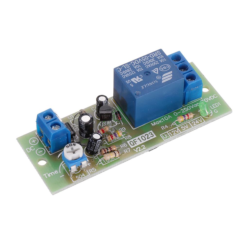
20pcs QF1023-A-10S Timing Relay Delay Switch Relay Delay Timer Switch Timing Relay 10S Adjustable
$96.74Relay ModuleAdd to cartSpecificationsWorking voltage:12V DCDelay length:0-10SAccuracy:1/100Error:2%Delay:using single chip delayPCB size:70*26*18mmInstallation hole center distance:64mmAperture:3mmFunction:Turn on the relay immediately after power-on, and automatically break after a period of time;Special reminder:This is not a power-off delay disconnect module, the relay will be disconnected immediately when the input power is disconnected.Package Included20 x QF1023-A-10S Timing Relay Delay Switch Relay Delay Timer …


Customers Also Viewed
DC 0-300V 500A Voltage Current Panel Meter Digital Blue Red Dual LED Voltmeter Ammeter with 500A/75mV Shunt
$48.10Electronic Accessories & SuppliesAdd to cartFeatures-2 in 1 function Voltmeter Ammeter, Easy install.-This meter test of Voltages and Amps, power supply can taken from the test circle, no additional power supply-Power supply DC 4.5V – 30V range (Attention:The maximum of input voltage cannot be exceed of 30V, otherwise would be burnt)-Display Range:DC 0V – 300V 0-500A (Please don’t exceed the …
3Pcs AC 220V 50A Power Amplifier Filter Power Supply Eliminate DC Power Filters for Toroidal Transformer
$28.05Module ComponentsAdd to cartProduct DescriptionThis product is connected in series with AC220V live wire. A 50A high-current rectifier bridge is used in series to eliminate the DC component more thoroughly.It can effectively eliminate the abnormal noise of the transformer caused by the DC component in the power grid (especially the sound of the toroidal transformer).Size:65MMX60MMx28MMType:Plug-in typePackage included3Pcs Filter …
5V WiFi Remote Garage Door Opener Controller Work with Alexa & IFTTT Google home Wireless Remote Control Switch
$21.86Smart ModuleAdd to cartNew toy for makers who want to build their own smart home system OverviewThe wireless switch supports inching /self-locking mode. You can add the device to the APP eWeLink to remote control connected home appliances or devices. In self-locking mode, you can remote turn on/off connected devices immediately. When in inching mode, you have two …
10pcs 3.7V 9V 5V 2A Adjustable Step Up 18650 Lithium Battery Charging Discharge integrated Module
$20.24Boost & Buck ModuleAdd to cartFeatureInput voltage:4.5-8VOutput voltage:continuous adjustable 4.3-27V (Counter clockwise to boost voltage)Charging voltage:4.2V Charging current:up to 1ADischarge current:the maximum 2AOutput reference maximum current:5V 1.4A, 9V 0.8A, 12V 0.6AQuiescent current:about 0.5 mAOvershoot protection:YesOver discharge protection:None (also can be said yes, because 2V cut-off boost but does not block the output, output has 2V)Deadline boost:2V, depending on whether added …


Recently Viewed Products
-
 50pcs WITRN-POW001 Multi-function Adapter Board Voltage and Current Measurement for Type-C USB A USB C MiniUSB MicroUSB 3.5 DC 5.5x2.1 DC 5.5x2.5 DC $53.82
 -
 10pcs WXD3-13-2W Precision Potentiometer 10K 10K Ohm Wirewound Multi-Turn Potentiometer $26.61
 -
 ATOMSTACK 3 Axis GRBL Control Panel Board Laser Box Motherboard for DIY Laser Engraving Machine CNC Controller Stepper Motor Driver Board $141.74
 -
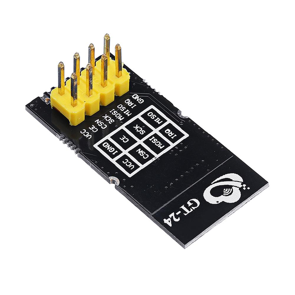 3pcs GT-24 Digital Wireless Module 2.4G NRF24L01 PA LNA industrial Grade 1100M Long Distance $17.20
 -
 220V 7g Ozonater Ozone Generator with Ceramic Plate for Water Plant Air Cleaner $60.09
 -
 5Pcs 2.54mm FC-8P IDC Flat Gray Cable LED Screen Connected to JTAG Download Cable $6.36
 -
 3pcs 24V XH-W3002 Micro Digital thermostat High Precision Temperature Control Switch Heating and Cooling Accuracy 0.1 $34.33
 -
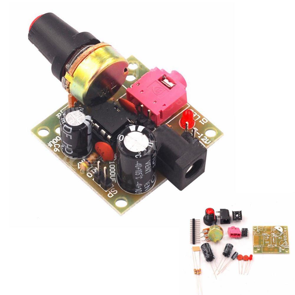 3pcs LM386 DC 3-12V 3.5mm Super Mini Audio Amplifier Board Module Audio Power Electronic Kit $12.68
 -
 10pcs Round Bottom Clear Plastic Test Tube with Cap Stopper 12X75/100mm $10.11
 -
 HAWEEL 28W High Power Portable Solar Folding Bag Charging Panel with Dual USB $153.05
Reviews
There are no reviews yet.