


10pcs Dual 2 Mode PWM Square Rectangular Signal Generator Control DC Stepper Motor Driver Board Adjustable Pulse Module
$75.25
Shipping:Standard Shipping about 10-25 business days
Secure Payment:Paypal,VISA,MasterCard
Size Conversion
Inches
Centimeters
Please according to your own measurements to choose your suitable size. The tags inside the items will show in our Asian (Type) size.
Feature
1. PWM signal generator, square rectangular signal generator
2. Used to generate square rectangular signals for controlling DC motor or stepper motor driver; used for servo motor, stepping motor, electric gripper, replacing PLC pulse, etc.
3. The supporting driver realizes dimming, speed regulation, control of solenoid , etc., but can not directly drive the load of the electric motor solenoid .
Product Highlights
1. Two modes can be selected
PWM mode – frequency (continuous), duty cycle, pulse number adjustable;
PULSE pulse mode – positive pulse width time, negative pulse width time, delay start time, and the number of pulses are adjustable.
2. With start and stop button, can control the output and stop of the signal
3. Wide voltage input 3.3-30V, with anti-reverse protection, 5.08mm terminal wiring
Technical parameters
1. Working voltage:3.3~30V, with anti-reverse protection
2. Frequency:1Hz~150KHz, accuracy about 2%
3. Duty cycle:0-100%, 1% stepping
4. Number of pulses:1-9999, or infinite (display ‘—-‘ stands for infinity)
5. Delay output time:0.000s-9999s, the can be set 1ms
6. Positive and negative pulse width length:0.000s-9999s, the can be set 1ms
7. Signal loading capacity:less than 30mA
8. Output signal amplitude:amplitude is equal to the supply voltage
9. Product size:60 x 32 x 10mm
10. Product Weight:18g
11. Packing:Anti-static bag
PWM mode (display has ‘%’ for PWM mode)
1. The factory default mode is PWM mode, FREQ+ and FREQ-key set frequency, DUTY+ and DUTY-button set duty cycle; short press STOP button control signal output or stop, stop output is 0, the screen displays “OUT” mark as There is output, otherwise it stops output; the default factory frequency is 1KHZ and the duty cycle is 50%.
If you want to switch to PULSE pulse mode, long-press the SET button (more than 6 seconds), do not release, you will see the screen change, ‘%’ disappears, it is PULSE mode.
2. PULSE pulse mode (No ‘%’ on the right side of the display is displayed in PULSE mode)
The P+ and P- buttons set the positive pulse width time, the LCD screen shows up, the N+ and N- buttons set the negative pulse width time, the LCD screen displays downwards, the unit is seconds; short press the STOP button to control the signal output or stop, stop output It is 0, the screen displays “OUT” mark as output, otherwise it stops output; the default factory positive pulse width is 0.5 second, and the negative pulse width is 0.5 second.
Pulse number and delay time setting – In PULSE mode, press and hold the SET button for 2 seconds and then release, enter the pulse number and delay time setting interface, the screen displays SET, it will be turned off and cleared after entering. Output pulse; P+ and P- buttons set delay time, N+ and N- buttons set pulse number, factory default delay time is 0 seconds, pulse number is infinite (display —-); Press the button for 2 seconds, automatically return to the pulse interface, press the STOP button, after the delay setting time, start to send the set number of pulses, if the number of pulses is sent, it will automatically output 0, if the period is not sent, press the STOP button. The output pulse will be turned off and cleared, and the number of pulses set will be issued each time it is started.
Application Operation Examples
1. PWM output 20KHZ, 60% duty cycle:Select PWM mode, the frequency is set to 20.00, and the duty ratio is set to 060%.
2. The output is turned on for 0.6 seconds and turned off for 0.2 seconds. Infinite loop:select PULSE mode, the positive pulse width is set to 0.600, the negative pulse width is set to 0.200, the delay time is set to 0.000, and the number of pulses is set to — -.
3. Power on or press the start button, delay 5 seconds, then the output is turned on for 0.6 seconds, off 0.2 seconds, infinite loop:select PULSE mode, positive pulse width is set to 0.600, negative pulse width is set to 0.200, delay The time is set to 5.000 and the number of pulses is set to —-.
4. Power on or press the start button, delay 5 seconds, then output high level 10ms low level 10ms pulse 100:select PULSE mode, positive pulse width is set to 0.010, negative pulse width is set to 0.010, delay The time is set to 5.000 and the number of pulses is set to 0100.
5. Power-on delay for 10 seconds, then permanently output signal:select PULSE mode, the positive pulse width is set to a number greater than 0, the negative pulse width is set to 0, the delay time is set to 10.00 seconds, and the pulse number is infinite. (—-).
6. Other applications can explore or consult customer service
All setup parameters are not lost when they are turned off.
Package includes
10 x PWM signal generator
| Weight | 0.19 kg |
|---|
Related products
Schumann Wave Generator 7.83Hz 20W Power with Housing Low Frequency Generator 7.83HZ Sine Wave
$54.66Generator ModuleAdd to cartParameterProduct name:Schumann wave generator/very low frequency generatorMainboard power supply:DC 24V /2AOutput power:peak 20WAdapter power supply parameters:AC 100-240V 50HZOutput frequency:7.83HZOutput waveform:sine waveMotherboard size:9CM length * 5CM width * 2.5CM heightFeaturesSchumann wave itself does not directly act on audio or video products to improve the sound quality and picture quality, but on the space environment, the human …
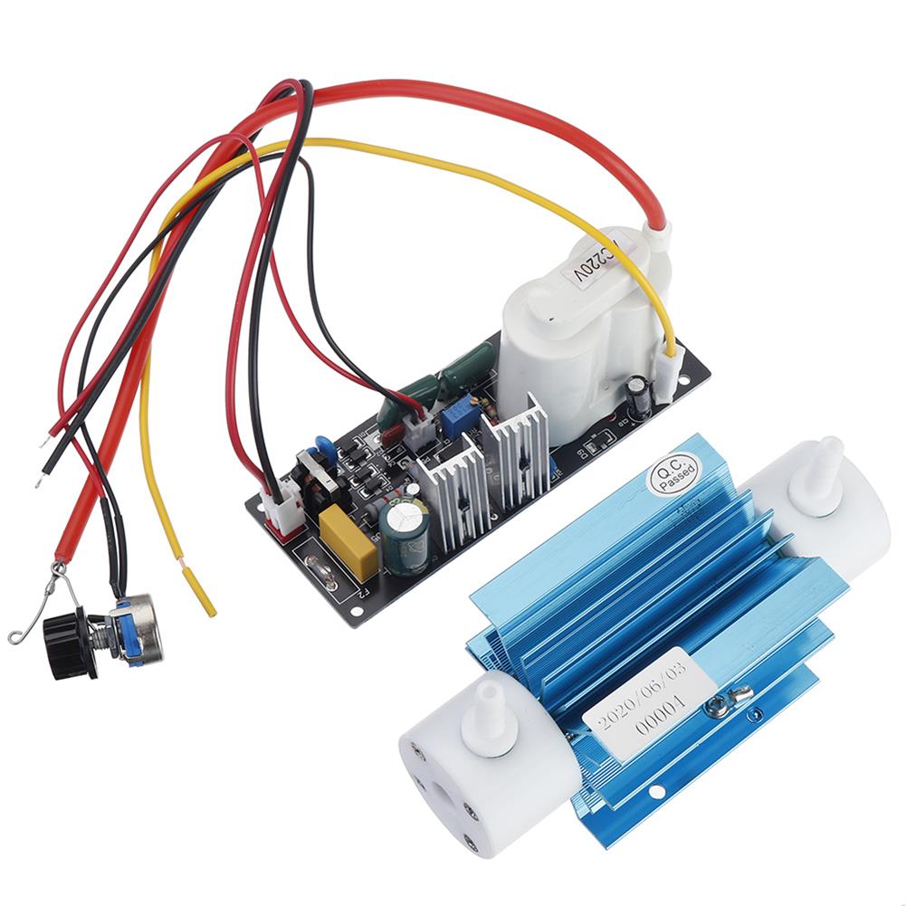
110V 5g Silica Tube Ozone Generator Module Ozone Output Adjustable Open Power Pack with Accessory
$74.34Generator ModuleAdd to cartSpecificationsInput Voltage:AC110VOzone tube dimension/ Weight:135x52x53mm / 0.3kgPower Pack dimension/Weight:152x72x68mm0.6kgPower consumption:3-40WCooling Style:air coolingAccessory:silicone tube 2 meter (6*8mm, since the ozone generator gas nozzle is 7mm), air stone 2 pcs (1 round and 1cylinder), air pump 5L/min 1pc. Ozone yield changes with the input gas flowFunction1. Sterilization:destroy variety of bacteria & viruse efficiently without secondary pollution.2. Detoxification:effectively …
20pcs NE555 Pulse Frequency Duty Cycle Square Wave Rectangular Wave Signal Generator Adjustable 555 Board NE555P Module
$60.18Generator ModuleAdd to cartFeatures-Size:3.5CM * 3.6CM-The main chip:NE555;-Input voltage:5V-15VDC. 5V power supply, the output current can about 15MA; 12V power supply, the output current can be so 35MA;-Input Current:100MA-Output amplitude:4.2V V-PP to 11.4V V-PP (depending on the input voltage, the output amplitude is not the same)-Maximum output current:15MA (5V power supply, V-PP greater than 50%), 35MA (12V power …


Customers Also Viewed
28.35ct 20x15mm Purple Oval Elliptical Cut Gemstone VVS AAA Jewelry Loose Gems Decorations
$20.24Lab Clamp & StandAdd to cartSpecificationsMaterial:ZirconColor:PurpleSize:20x15mmWeight:28.35ctClarity:VVS AAAShape:OvalFeatures– Transparent, bright;– Color is bright and the purity is positive;– Wide range of use;– Application for jewelry.Package Included1 Pcs x Purple Oval Cut Gemstone
5pcs CJMCU-250E BMA250E Sensor Module 3-axis Low G Acceleration Sensor Triaxial Accelerometer SPI IIC interface
$32.02Sensor & Detector ModuleAdd to cartFeatureThe BMA250E is a triaxial, low-g acceleration sensor with digital output for consumer applications. It allows measurements of acceleration in three perpendicular axes. An evaluation circuitry (ASIC) converts the output of a micromechanical acceleration-sensing structure(MEMS) that works according to the differential capacitance principle.Package and interfaces of the BMA250E have been defined to match a multitude …
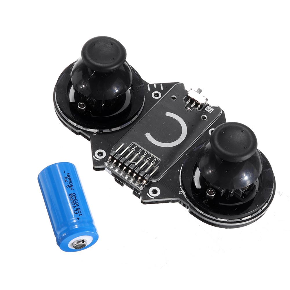
JoyC Rocker Sensor Switch Module STM32F030F4 Control Chip Game Handle I2C Wireless Joystick Device
$54.05Motherboard & Development BoardAdd to cartDescriptionJoyC is a rocker module designed for the M5StickC.It supports two-hand operation. Embedded STM32F030F4 main control chip, using I2C communication protocol and host M5StickC for data transmission. The ran ge of the joystick is 0~200, there are 12 RGB LEDs under the left and right joysticks, and the bottom of the joystick is equipped with …
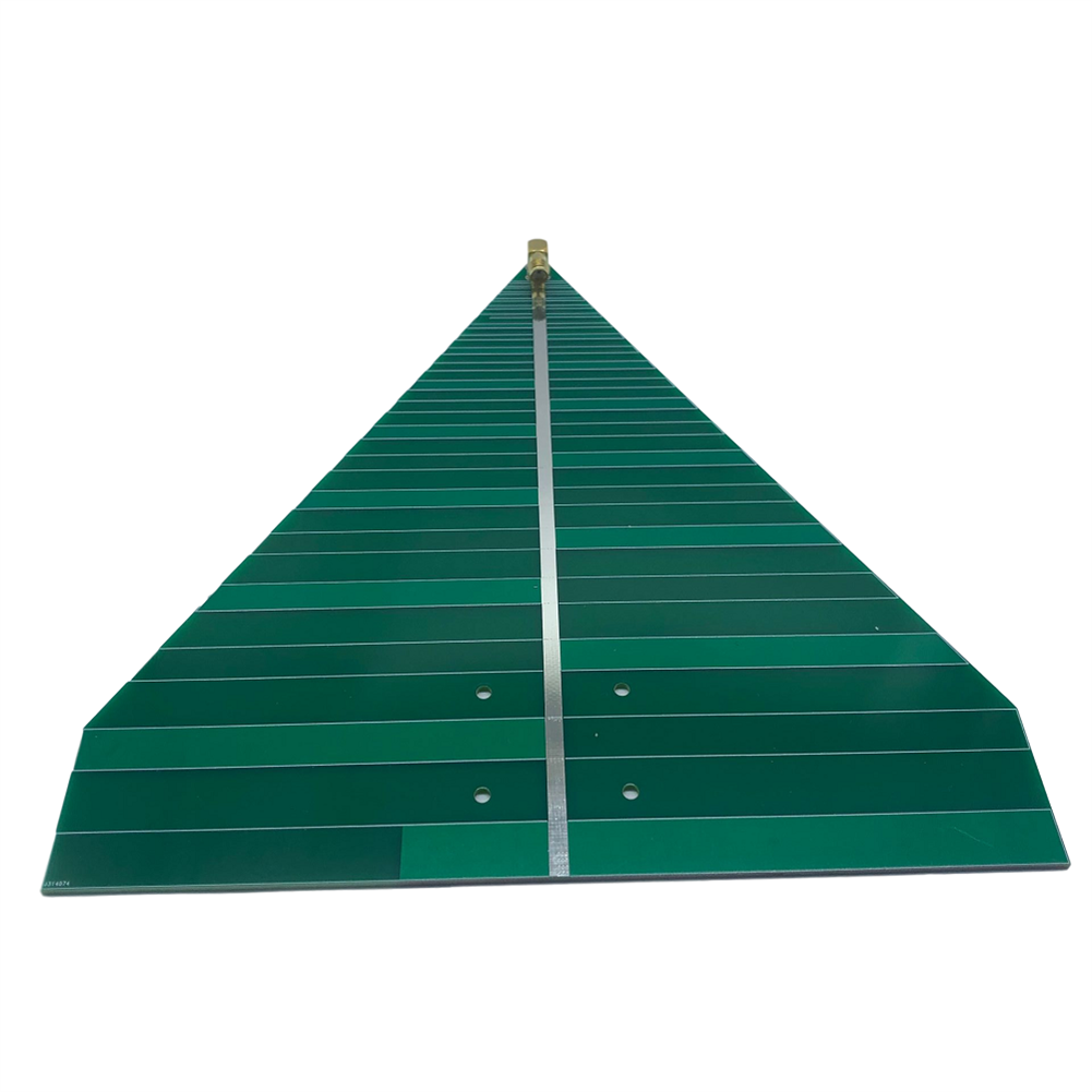
600-6000MHz UWB WiFi Ultra-wideband Log Periodic Antenna
$32.00RF amplifierAdd to cartSpecification1. Antenna frequency:600-6000MHz2. Antenna standing wave:less than 2 (typical value)3. Antenna polarization:directional linear polarization4. Antenna gain:6-7dB5. Power capacity:50W6. Dimensions:20≠20CM7. Weight:74 g8. Connector form:SMA-K (standard female, outer screw and inner hole)Package included1 x Antenna


Recently Viewed Products
-
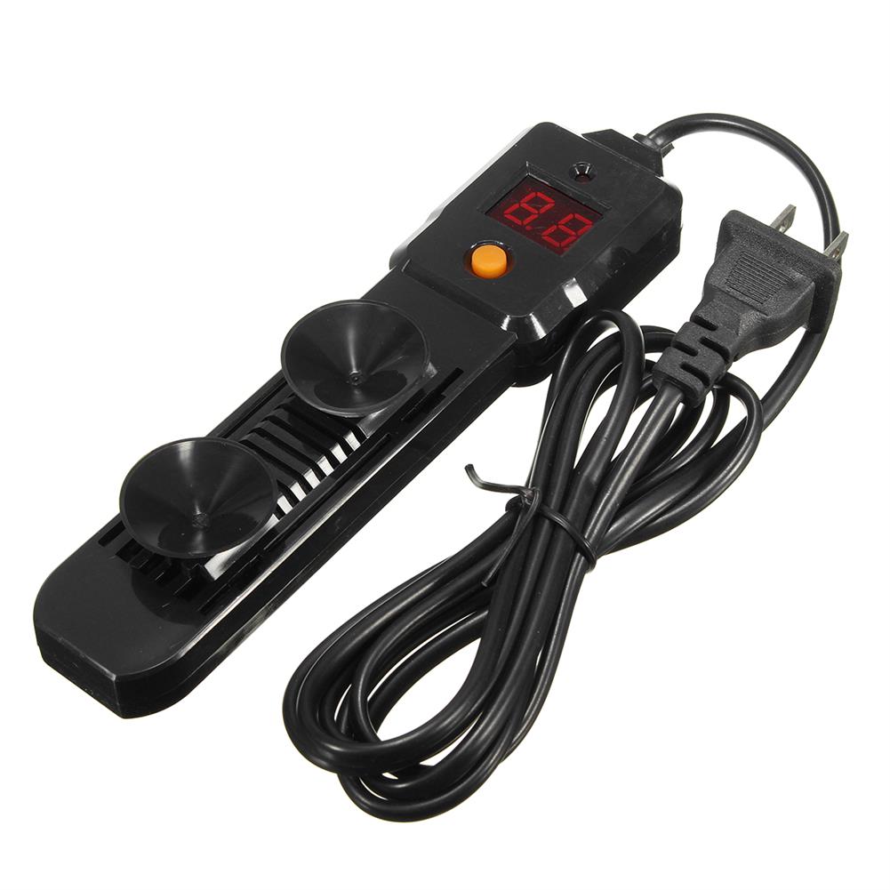 220V 100W Adjustable Submersible Aquarium Water Heater thermostat Fish Tank $32.87
 -
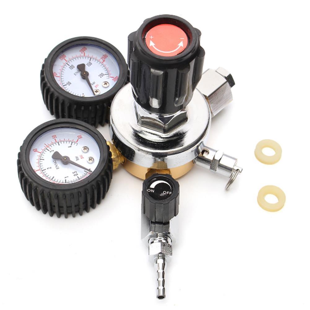 CO2 Regulators Pressure Reducer for Beverage Beer W21.8 Double Gauge Regulator $131.61
 -
 AC 85-265V To DC 24V 4A-6A Switching Power Supply Module Board AC-DC Transformer $17.24
 -
 MD1506 GSM/CDMA/Mobile Phone Built-in Ceramic Antenna Omni-directional Wireless 3G/4G/GPRS Antenna Module for Smart Home $4.81
 -
 Mini 12V Power Supply Tesla Coil Module DIY Spare Space Lighting Tech Electronic Production Kit $8.73
 -
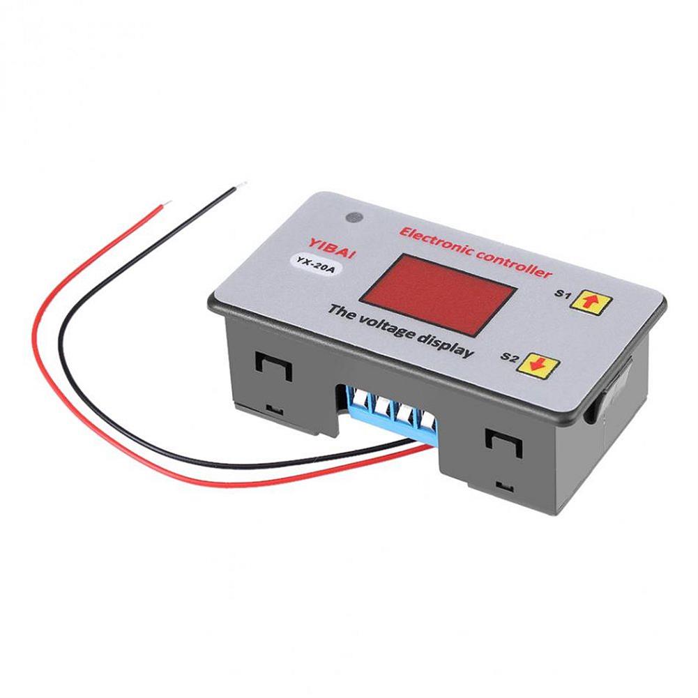
 12V/24V/36V LCD Display Lead Acid Battery Capacity Meter Voltmeter Power Monitor $38.46
 -
 YX-815 Battery Charging Controller Battery Protection Module for Undervoltage Control Over-discharge Protection Board 6V-48V $19.67
 -
 MH-Z19B infrared CO2 Sensor for CO2 Monitor NDIR Gas Sensor CO2 Gas Sensor 0-5000PPM $70.35
 -
 20pcs 5V 2.1A Output UPS Power DIY Charger Board Step Up DC to DC Converter Module for 3.7V 18650 Lithium Battery $148.58
Reviews
There are no reviews yet.