


5pcs Electronic DIY LED Dimming Lights Series and Parallel Circuit Technology Small Production Kit
$16.60
Shipping:Standard Shipping about 10-25 business days
Secure Payment:Paypal,VISA,MasterCard
Description
The purpose of the experiment
1. Understand and recognize the light-emitting diodes and illuminate the light-emitting diodes (LEDs);
2. Understand the role of understanding resistance, series and parallel resistance;
3. Understand the self-locking switch;
4. Understand and recognize adjustable resistors and use adjustable resistors;
Experimental steps
Step 1:The long leg of the light-emitting diode (LED) is the positive pole, and the short leg is the negative pole. First, the long wire of the LED is connected to the black wire (negative electrode) of the battery case, and the short leg of the LED is connected to the red wire (positive electrode) of the battery case. At this time, the light emitting diode (LED) is not lit. Then send it over again, let the long leg of the LED connect to the red line of the battery box, and the short leg of the LED is connected to the black line of the battery box. At this time, the LED lights up, indicating that the LED is in one-way operation and the single-pass characteristic of the diode .
Step 2:In the circuit of the experimental step 1, a resistor of 220 ohms is inserted in series, and the brightness of the LED lamp is lowered, and the resistance hinders the current.
Step 3:Connect a 220 ohm resistor in parallel with the resistance in the circuit of the experimental board 2. The brightness of the LED is increased, indicating that the total resistance of the resistor in the circuit is reduced after the resistors are connected in parallel.
Step 4:Change the two resistors of the experimental step 3 from parallel to series. After the series connection, the brightness of the LED lamp is the lowest. After the series connection of the resistors, the total resistance of the resistor in the circuit increases.
Step 5:Replace the original resistor with a potentiometer. The potentiometer has 3 feet, and the resistance of pins 1 and 3 is fixed. The resistance of pins 1 and 2, 2 feet and 3 feet can be changed by adjusting the potentiometer knob. When experimenting, you can pick up 2 of them. The foot has to experiment many times, adjust the potentiometer knob to observe the change of LED brightness, so that you can fully understand the potentiometer.
Step 6:Know the self-locking. Press and wait for the light to be on, then press the light to turn off.
Package included
5 x DIY LED Dimming Lights Technology Small Production Kit
| Weight | 0.135 kg |
|---|
Related products
Transparent Module Case Housing Shell for Upgrade DIY EC1515B DS1302 LED Electronic Clock Kit
$13.11DIY Electronic KitsAdd to cartTransparent Case Housing Shell For Upgrade DIY EC1515B DS1302 LED Electronic Clock Kit Feature This is for ID 1053190 only, used as spare parts and maintenance. The DIY clock kit is not included. Color:Transparent Note The color of the new case is blue as follwing picture, which is not affect the function. Package included 1 …
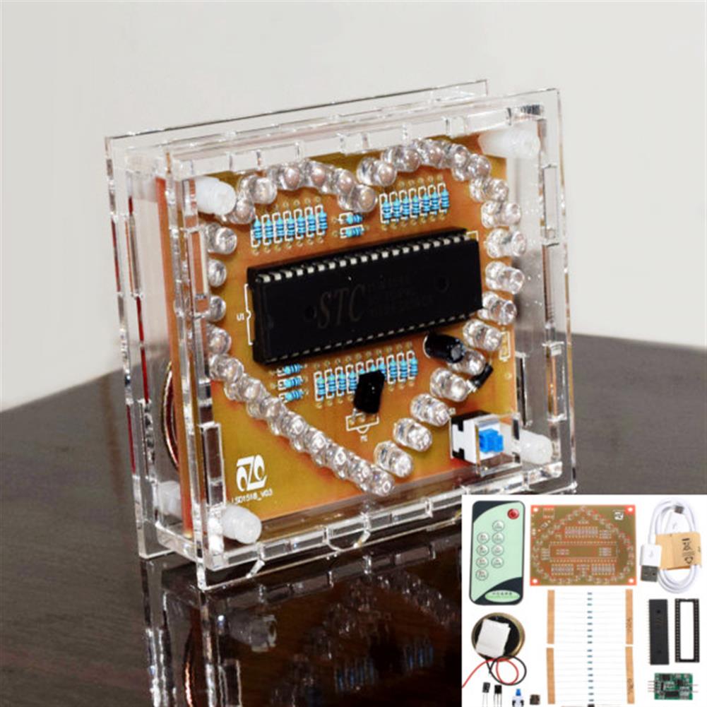
DC 5V DIY Colorful MP3 Music Heart-shaped RGB LED Flash Kit
$28.62DIY Electronic KitsAdd to cartVideo Feature Size:92 x 79.5 x 29mm model:STC15W408S Operating voltage:DC 5V (Or USB) Remote control:9-key infrared remote control (need to be aligned with the infrared receiver, no need pairing) Music:You can replace the music, you can also insert the U disk playback (only supports MP3 format) Sound output:8ohm 1W Measured speaker distance:65dB (1M) Speaker size:4cm …
DC 5V DIY Colorful MP3 Music Heart-shaped RGB LED Flash KitRead More
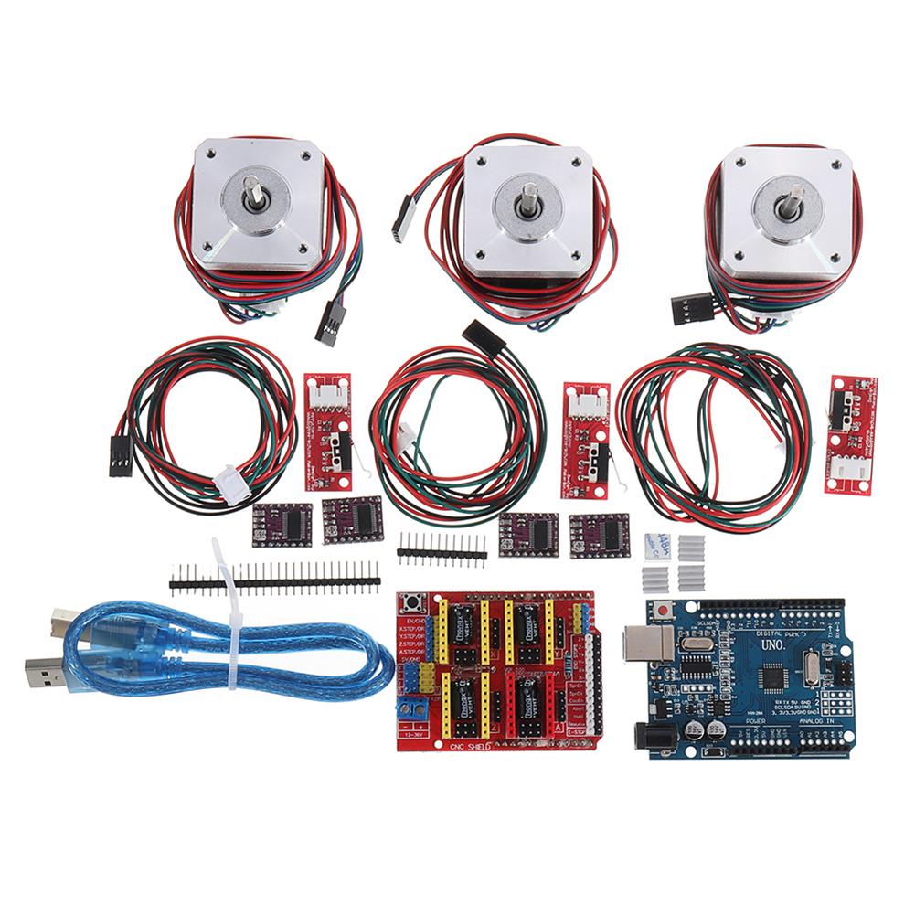
CNC Kit with UNO + Shield + Stepper Motor DRV8825 Endstop A4988 GRBL
$125.66DIY Electronic KitsAdd to cartThe kit contains following items 1x UNO R3+CH340G Board. It’s not official board but it’s compatible with all software and hardware. Licensed under Creative Commons Attribution Share-Alike license. 1X 40inch Gold plated/shielded USB cable w/noise suppressor. Essential for stable connection and printing. 1x CNC shield 3X Zyltech 1.5A 0.42 N.m stepper motors 3X Mechanical endstop …
CNC Kit with UNO + Shield + Stepper Motor DRV8825 Endstop A4988 GRBLRead More
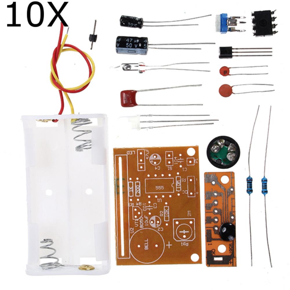
10Pcs DIY Touch Vibration Alarm Kit Electronic Training Teaching
$34.22DIY Electronic KitsAdd to cartWorking principleThe touching vibration alarm consists of touch trigger circuit, vibration trigger circuit and alarm circuit. The 555 time base circuit U1 forms the typical monostable operating mode. The transient time is determined by the values of RP1, R2 and C2.Usually the circuit is in steady state, 555 time base circuit 3 pin output low, …
10Pcs DIY Touch Vibration Alarm Kit Electronic Training TeachingRead More

Customers Also Viewed
M5Stack 8-Way Servo HAT STM32F030F4 Microcontroller Control Board for M5StickC ESP32 IoT Development Board
$16.96Other Module BoardAdd to cartDescription 8Servos HAT is an 8-way servo control board compatible with M5StickC. The brains of the borad is the STM32F030F4 microcontroller which communicates with M5StickC through I2C. In order to ensure that multiple servos can work at the same time, the HAT is equipped with a separate 16340 battery base for an external and independent …
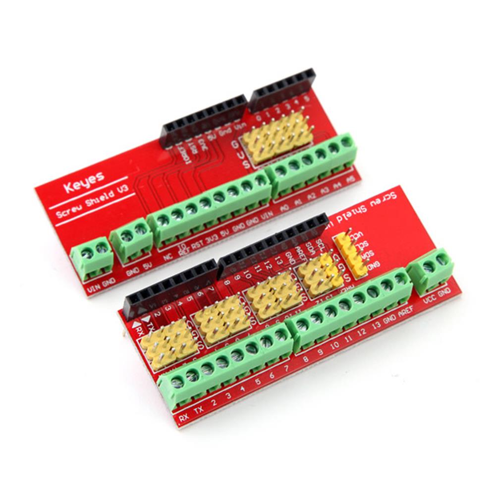
Screw Shield V3 Terminal Expansion Board for UNO R3
$8.73Expansion Board & ShieldAdd to cartScrew Shield V3 Terminal Expansion Board For Compatible UNO R3DescriptionWe use to do work, always feel bad connection on the port. Either use bread plates into line, either using the sensor cable expansion board with Dupont, feel less reliable, and now we launch a terminal expansion board can be directly screwed onto the thread of …
Screw Shield V3 Terminal Expansion Board for UNO R3Read More
CH340G RS232 Upgrade USB to TTL Auto Converter Adapter STC Brush Module
$6.55Converter BoardAdd to cartFeaturesThere are power light PWR, and TXD and RXD indicatorsReserve RTS, CTS location3.3V and 5V dual voltage selectionSupport XP/WIN7/WIN8/WIN10 systemAnti-short-circuit, anti-overcurrent, anti-reverse, anti-high voltage multiple protection.Package includes1 x Module
10pcs CJMCU-8575 PCF8575 Bidirectional IIC I2C And SMBus I/O Expander Expansion Board
$80.46Expansion Board & ShieldAdd to cartDescriptionHave you run out of I/O pins This great IC allows the user to expand up to 16 I/O using only two I/O for control! The PCF8575C is controlled through an I2C interface and features 16-bits of quasi-bidirectional input/output pins.Package included10 x Module
5pcs 30MA 5V 0.15W Mini Solar Panel Epoxy Board
$16.04Smart Robot & Solar PanelAdd to cartSpecifications– Maximum power:0.15 (W)– Working current:0-30MA(Depending on the intensity of sunlight)– Working voltage:5 (V)– System voltage:5.5 (V)– Open circuit voltage:5.5 (V)– Short circuit current:0.05(A)– Dimensions:about 53*30 (mm)– Weight:about 12g– For:DIYer– Quantity:5PcsPackage Included5 x solar panel
20Pcs Keyes Brick Finger Heartbeat Module(Pad hole) with Pin Header Board Analog Signal
$55.28Sensor & Detector ModuleAdd to cartDescriptionThis module is fully compatible with ARDUINO single-chip microcomputer, and its connection port is also compatible with Arduino sensor expansion board. This module mainly includes infrared transmitter and photosensitive receiver. The infrared transmitter is on one side of the finger, and the photosensitive receiver is on the other side of the finger; the photosensitive receiver …
20Pcs Keyes Brick Finger Heartbeat Module(Pad hole) with Pin Header Board Analog SignalRead More


Reviews
There are no reviews yet.