


WZ5012L 50V 12A 600W Programmable Digital Control Step-down DC Stabilized Power Supply Module with Adjustable Voltage and Current LCD Display
$48.10
Shipping:Standard Shipping about 10-25 business days
Secure Payment:Paypal,VISA,MasterCard
>>>Manual:Click here to open
Feature
1. LCD can display input/output voltage, output current/output power/output capacity/output time;
2. Numerical control adjustment, precise and fast, step-down output, output voltage 0-50.00V arbitrary adjustment, limit current 0-12.00A arbitrary adjustment;
3. The output end does not burn when it is poured backwards;
4. The module can be set to turn on/off by default;
5. Possess a variety of software protection mechanisms, and the protection threshold is adjustable. After the working parameters of the module exceed the protection threshold, the output is automatically turned off;
6. Using synchronous rectification technology, high conversion efficiency:efficiency above 90%;
7. Enlarge the heat sink and install a fan to enhance heat dissipation.
Model:WZ5012L
Display:LCD display
Input voltage range:6-55.00V
Input voltage resolution:0.01V
Output voltage range:0-50.00V
Output voltage resolution:0.01V
Output current range:0-12.00A
Output current resolution:0.01A
Output power range:0-600.0W
Input voltage accuracy:÷(1%+5 words)
Output voltage accuracy:÷(0.3%+5 words)
Output current accuracy:÷(0.5%+5 words)
Typical output ripple:150mV peak-to-peak value
Normal working temperature range:-10→~40→
Capacity measurement range:0-999.9AH
Statistical error of capacity energy:÷2%
Statistical time range:0-100 hours
Step-down working mode:differential pressure>0.05%+1V
Bare weight:about 199g
Product size:Panel 79X43X42mm
With packaging:about 242g
Motherboard:106x76x40mm
Soft start:Yes
protection mechanism
Input undervoltage protection (5.8-50V adjustable, default 5.8V)
Output overvoltage protection (0-51.00V adjustable, default 51V)
Output overcurrent protection (0-12.10A adjustable, default 12.10A)
Timeout protection (0-100h adjustable, closed by default)
Over-capacity protection (0-999.9Ah adjustable, closed by default)
Instructions
1. Switch display parameters-in the normal interface, short press SW to switch the lower display of the display. The display content is switched between current A, power W, capacity Ah, and time h. Long press the SW button to switch the upper display of the screen, and the display content is switched between input voltage IN and output voltage OUT.
2. Set the output voltage value-short press the U/I button in the normal interface to enter the set voltage constant current interface. You can see that a certain digit of the set output voltage value is flickering. Turn the rotary encoder left and right to adjust it to increase or decrease. Short press the rotary encoder to select which bit of the output voltage is set. After the setting is completed, short press the U/I button twice to return to the normal interface. Or it will automatically return to the normal interface after 10s of stopping operation.
3. Set the constant current value (that is, the maximum current value that the module allows to output)-short press the U/I button in the normal interface to enter the setting voltage constant current interface. Short press the U/I button again to switch to the constant current value setting. You can see that a certain digit of the constant current value is flickering. Turn the rotary encoder left and right to adjust the value to increase or decrease. Short press the rotary encoder to select which bit of the constant current value is set. After the setting is completed, short press the U/I button to exit the setting voltage constant current interface and return to the normal interface. Or it will automatically return to the normal interface after 10s of stopping operation.
4. Set the default on/off state of the module when it is powered on-long press the U/I button in the normal interface to enter the parameter setting interface. It can be seen that OPEN OFF or OPEN ON is displayed. OPEN OFF means that the output is turned off by default when power on, and OPEN ON means that the output is turned on by default when power on. Long press the rotary encoder to switch between two states. After setting, long press the U/I button to return to the normal interface.
5. Set the protection parameter on state and threshold value-in the normal interface, long press the U/I button to enter the parameter setting interface. Short press the SW button until the protection parameter you want to set appears. LUP――undervoltage protection threshold; OUP――overvoltage protection threshold; OCP――overcurrent protection threshold; OAP――overcapacity protection threshold; OHP overtime protection threshold. Short press the rotary encoder to select which bit of the protection parameter you want to set. Long press the rotary encoder to set the protection parameters on or off (Only timeout protection and over-capacity protection can be set on/off, and other protection parameters are turned on by default.). Rotate the encoder left and right to make the parameter bigger and smaller. After setting, long press the U/I button to return to the normal interface.
6. Calibrate voltage and current-press and hold the U/I button in the normal interface to enter the parameter setting interface. Short press the SW button until an interface with Zero appears, with the symbol of Zero+OUT+A, long press the rotary encoder to complete zero calibration. Short press the SW button, the CAL parameter interface appears. The one with the CAL+IN+V symbol is the calibration input voltage interface; the one with the CAL+OUT+V symbol is the calibration output voltage interface; the one with the CAL+OUT+A symbol is the calibration output current interface. Rotate the encoder left and right to adjust the size of the parameter to the actual value measured with a multimeter. After the adjustment is completed, long press the rotary encoder to confirm the adjustment is completed, and the parameter value is not flashing at this time. Long press the U/I button to return to the normal interface.
Note:In order to ensure the accuracy of calibration, calibration voltage-voltage above 12V can start calibration; calibration current-current above 1A can start calibration.
Precautions
1. It is strictly forbidden to connect the positive IN+ and negative IN- of the module input reversely, and it is forbidden to short-circuit the input IN- and the output OUT-, otherwise the module may burn out.
2. Please ensure that the power of the power supply is always greater than the power required by the output load!
3. This module is a step-down module, the input voltage must be higher than the output voltage, and a certain margin is left. If you want to output at full load, the input voltage should be 55V.
4. The high-power use of this module will cause serious heat and high temperature, be careful of burns! When using high power for a long time, please pay attention to ventilation and heat dissipation!
5. The module has an input under-voltage protection function, the default is about 5.8V (can be set), when the value is lower than this value, it will automatically cut off the output (note that the voltage at the module port is lower than the under-voltage protection threshold, when the input current is compared When it is large, don’t ignore the partial voltage on the input wire).
Package includes
1 x WZ5012L
| Weight | 0.25 kg |
|---|
Related products
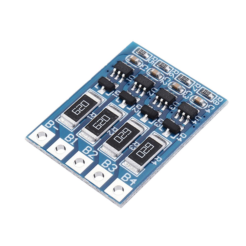
5pcs 4S 14.8V/16.8V 18650 Polymer Lithium Battery Protection Board Balanced Function Discharge Shunt Balance 4.2V 66mA
$15.03Power Supply ModuleAdd to cartUsageFor non-balanced rechargeable lithium battery pack, the charge balance makes the battery pack in the battery pack at the same time fully charged.SpecificationsEqualization Voltage:4.2VEqualizing Current:66mAProduct Size:26 * 20.5 * 2.4mmNotedThe balance sheet does not charge and discharge protection function, can not replace the protection board, when the battery is charged, the first fully charged battery …
RIDEN UM34 USB 3.0 Type-C DC Voltmeter Ammeter Voltage Current Meter
$55.81Power Supply ModuleAdd to cartUM34 Technical ParameterProduct Model:UM34 Display screen:1.44 Inch color LCD displayVoltage measurement range:4-24.000V Voltage measurement resolution:0.01VCurrent measurement range:0-5.0000A Current measurement resolution:0.001ACapacity accumulation rannge:0-99999mAh Voltage measurement accuracy:±(0.2%+1digit)Energy sccumulation range:0-999.99Wh Current measurement accuracy:±(0.8%+3digits)Load impedance range:0.8Ω-9999.9Ω Time measurement range:0-99h59min59sTemperature range:-10→-100→/0-200 Temperature measurement error:±3→/±6Screen brightness setting:0-5 levels Auto screen off time:0-9minsVoltage graphing range:0-24.00V Current graphing range:-4.000ARefresh rate:2Hz Quick charge recognition …
RIDEN UM34 USB 3.0 Type-C DC Voltmeter Ammeter Voltage Current MeterRead More
20pcs 4S 14.8V/16.8V 18650 Polymer Lithium Battery Protection Board Balanced Function Discharge Shunt Balance 4.2V 66mA
$51.42Power Supply ModuleAdd to cartUsageFor non-balanced rechargeable lithium battery pack, the charge balance makes the battery pack in the battery pack at the same time fully charged.SpecificationsEqualization Voltage:4.2VEqualizing Current:66mAProduct Size:26 * 20.5 * 2.4mmNotedThe balance sheet does not charge and discharge protection function, can not replace the protection board, when the battery is charged, the first fully charged battery …
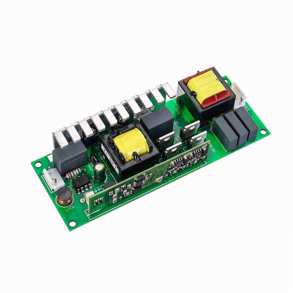
230W 7R DJ Disco Stage Head Light Lamp Moving Beam Ballast Power Supply Module
$45.91Power Supply ModuleAdd to cartTechnical SpecificationsMini size, compact design.sturdy and durable.Easy to use and convenient to operate.Application:Commercial, Engineering, Indoor, Outdoor, Professional, SailingFeatures and BenefitsMaterial:PCBVoltage:110-220VWattage:230WType:7R BallastLength:13cm/5inchPackage Includes1 x Power Supply ModuleNotice1. Please allow 1-3cm error due to manual measurement.Pls make sure you do not mind before you bid.2. The color may have different as the difference display,pls understand.


Customers Also Viewed
3Pcs 0.96 inch 4Pin White IIC I2C OLED Display Module 12864 LED
$38.88Display ScreenAdd to cartFeatureOLED Driver IC:SSD1306Resolution:128 x 64Visual Angle:>160°Input Voltage:3.3V ~ 6VCompatible I/O Level:3.3V, 5VMini Size:2.7 x 2.8cmOnly Need 2 I/O Port to ControlFull Compatible , 51NoteIf you decide to buy OLED display, you must confirm that you can make it work by yourself, we’ll haven’t any technology support. Thanks for your understanding and support.Package included3 x 0.96 …
3Pcs 0.96 inch 4Pin White IIC I2C OLED Display Module 12864 LEDRead More
Micro:Bit bluetooth 4.0 Low Energy Open Development Board for Programming
$60.06Raspberry Pi & Orange PiAdd to cartOverviewThe micro:bit is an open development board that allows you to run code on it and have access to all of the hardware.You can use your micro:bit for all sorts of cool creations, from robots to musical instruments – the possibilities are endless.This little device has an awful lot of features, like 25 red LED …
Micro:Bit bluetooth 4.0 Low Energy Open Development Board for ProgrammingRead More
500mL 24/40 Glass Filtering Flask Lab Filtration Conical Flask Bottle Laboratory Glassware
$58.71Glassware KitAdd to cartDescription– Flasks are glass or plastic containers for storing or collecting chemical samples or solutions in scientific laboratories.– It shaped like a cone with a wide, flat base that narrows to a neck opening, which can be closed with a stopper or cap.SpecificationMaterial:Borosilicate GlassCapacity:500mLFlask Style:Filtering (vacuum)Feature– The neck is 24/40 Ground Joint.Package Included1 x Glass …
500mL 24/40 Glass Filtering Flask Lab Filtration Conical Flask Bottle Laboratory GlasswareRead More
AC 100W 40KHZ Ultrasonic Cleaning Power Driver Board with 50W 40K Transducer 220V
$98.40Driver ModuleAdd to cartSpecificationsPower:220V 100WPendulum:50W 40KHZApplies to:Low-power ultrasonic cleaning machine, household cleaning machine, ultrasonic generator built machine.Features1. The ultrasonic generator can monitor the power system frequency ultrasound power.2. According to different requirements of users, real-time adjustment of various parameters, the power, amplitude, and running time.Circuit board and vibration head (ceramic transducer) Wiring instructions1. The board can not no-load …
AC 100W 40KHZ Ultrasonic Cleaning Power Driver Board with 50W 40K Transducer 220VRead More
5pcs 3S 18650 4A 11.1V BMS Li-ion Battery Protection Board 18650 Battery Charging Module Charger Electronic DIY
$19.48Battery Protection ModuleAdd to cartSpecificationsCharging Voltage:12.6V-13VOvercharge Voltage Range:4.25V-4.35V ± 0.05VOverpressure Voltage Range:2.3V-3.0V ± 0.05VUpper Limit Operating Current:3A-4AUpper Limit Instantaneous Current:9A-10AQuiescent Current:less than 30uAInternal Resistance:less than 100mohmEffective Life:more than 30,000 hoursOperating Temperature:-40- +50 degreesStorage Conditions:-40- +80 degreesSize:53 * 16 * 3mmShort Circuit Protection:protection, delay self-recovery ApplicationsThe power range is suitable for the following products:massager battery pack, LED light standby power …
3pcs infrared Light IR Camera Control Board for Surveillance Camera Night Vision CCTV Accessories
$10.52Driver ModuleAdd to cartSize ConversionInchesCentimetersPlease according to your own measurements to choose your suitable size. The tags inside the items will show in our Asian (Type) size.SpecificationsCurrent:700mAVoltage input:12V DCVoltage output:1.7-12V DCSize:38MM * 38MMPotential:good night vision effect; rigorous design, stable performance and strong anti-interference.Use:Suitable for all kinds of infrared lamp board drive, suitable for 1-6 infrared lampFunction:It can be …


Reviews
There are no reviews yet.